Configuring VXs Studio inputs and outputs for AES67
 Updated
by
Bryan Jones
Updated
by
Bryan Jones
Scope
This document gives a brief overview of configuring audio to and from your callers on a VXs system, using AES67 audio sources. This guide is not an all-inclusive AES67 configuration document. For this document's purposes, we are assuming that you are installing VXs in an already existing AES67 environment.
PTP Clock
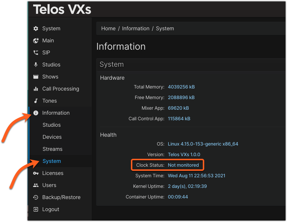
Please note that a PTP clock is required. At present, PTP is handled by the PTP4L configuration on the host computer. Therefore, it is typical for the VXs Information screen to show PTP Clock Status as Not Monitored.
Configuring Studios for AES67
The AES67 standard provides no mechanism for advertising channels like you might typically find in AoIP systems like Axia. Therefore, you will need to know the multicast addresses for channels used in VXs.
A couple of quick concepts
You will see the terms STUDIOS and SHOWS used frequently.
STUDIOS are the audio in and out. In other words, audio from the caller and the mix-minus back to the caller without respect to the phone number (or Line) used.
SHOWS are the phone lines applied to a STUDIO. You can apply any SHOW (phone lines) to any STUDIO (audio in/out)
There is also the concept of SELECTABLE vs. FIXED lines.
SELECTABLE lines are what is used most often in the US. You have six (or more) phone lines, and you "select" which line goes to the fader on the console.
FIXED lines are used to "fix" a single line to a single fader. Primarily used outside the US, if you had six phone lines, each line would be "fixed" to a specific fader on your console. Six lines = six faders.
Keep these in mind during your configuration.
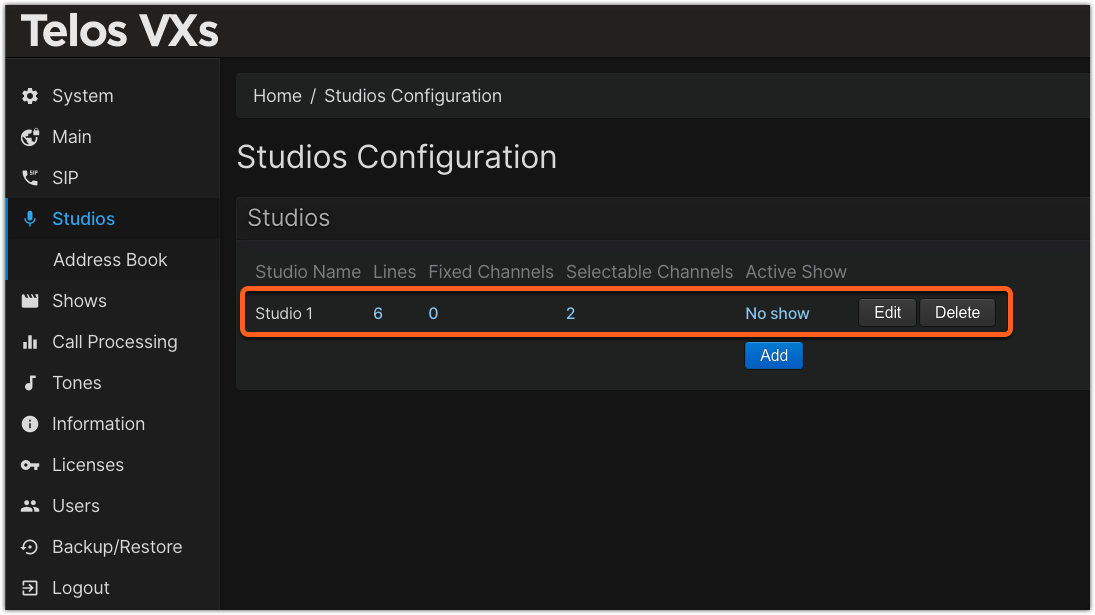
- From the main Web page of your VXs, click on Studios from the left side menu, then click the Add button.
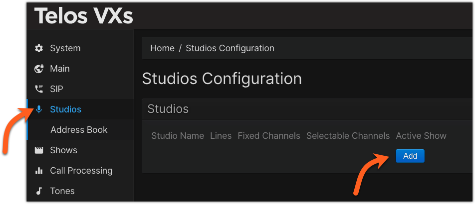
- Assign a Studio Name. In our example, Studio 1
- Assign some number of lines for this studio. We've chosen six in this example. (You can change this later)
- Click the Add button to the Left of Selectable Channels (alternately, used Fixed Channels if needed for your configuration). In our example, we clicked Add twice, to add two Selectable Channels (Faders) to be placed on the audio console.
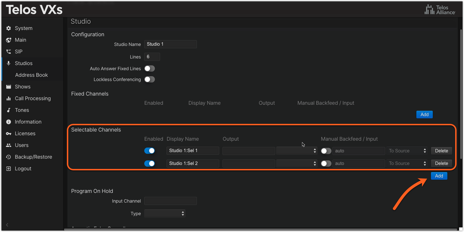
- Assign Display Names to each channel
- Assign multicast addresses in the Output section (this is the audio FROM the caller) and select AES67 Multicast from the drop-down list.
UDP port 5004 is assumed if no port is specified. If you need to use an alternate port, place a colon after the multicast IP address like 239.0.0.10:9000.
For AES67 Multicast output mode the format of the audio stream is as follows:
2 Channels, 48khz sample rate, 24bit depth, 1ms packet-time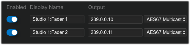 The multicast addresses used here are the address used to place the audio on the faders of your console.
- In the Manual Backfeed / Input section, enable the manual configuration slider, specify the multicast address for the backfeed, and select AES67 Multicast from the drop-down list (this is the mix-minus audio that goes back TO the caller).
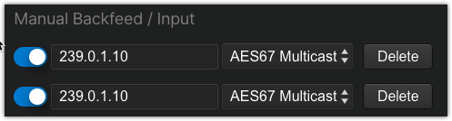 The multicast addresses here are derived from your console.
- Scroll to the bottom of the page and click Save.
When you return to the Studios menu, you will see one studio in your configuration. Repeat these steps for any other studios.
Let us know how we can help
If you have further questions on this topic or have ideas about improving this document, please contact us.