Replacing a broken On/Off bezel on a Fusion module
 Updated
by
Johnny Goldsmith
Updated
by
Johnny Goldsmith
Scope
This document pertains to the bezel that surrounds the On and Off buttons on the following Fusion modules:
- 2001-00329-000 Fusion 4-Fader Module (S)
- 2001-00330-000 Fusion Motorized 4-Fader Module (S)
- 2001-00331-000 Fusion Call Controller + 2-Fader Phone Module
- 2001-00332-000 Fusion Motorized Call Controller + 2-Fader Phone Module
- 2001-00379-000 Fusion Monitor + 2-Fader Module
- 2001-00380-000 Fusion Motorized Monitor + 2-Fader Module
- 2001-00419-000 Fusion Fader Panel
- 2001-00433-000 Fusion Mic Control/Headphone Selector Panel
- 2001-00435-000 Fusion Producer's Mic Control Panel
- 2001-00436-000 Fusion Mic Control Panel
- 2001-00477-000 Fusion 4-Fader Module (T)
- 2001-00478-000 Fusion Motorized 4-Fader Module (T)
If you're looking to replace the On or Off caps of a Fusion module, click here.
The Bezel
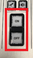
Sometimes the black frame surrounding the On and Off buttons of a module may crack or break because of something being dropped on the console. These bezels are replaceable in the field and we will cover the process below.
Our repair team can also replace them if you would rather send the module in for repair. To request an RA, click here.
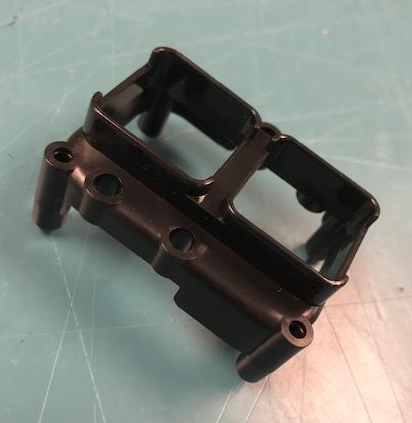
To place an order for a replacement bezel, you can contact customer support and ask for pricing and availability of part # 1453-00163, Fusion On/Off Button Bezel.
The Process
- Use a 2.5mm Allen wrench to remove the screws holding the module in place. Remove the module from the console by lifting the top away from the frame. Use caution as there is a ribbon cable connecting the module to the overbridge.
- Place the module face down on a protected surface and remove the bottom board from the rear of the module by unscrewing the 11 Phillips screws.
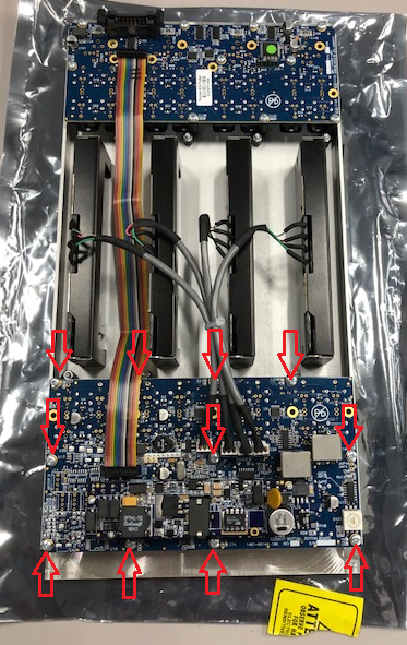
- Carefully pull the bottom board away, exposing the four On/Off bezels of the module.
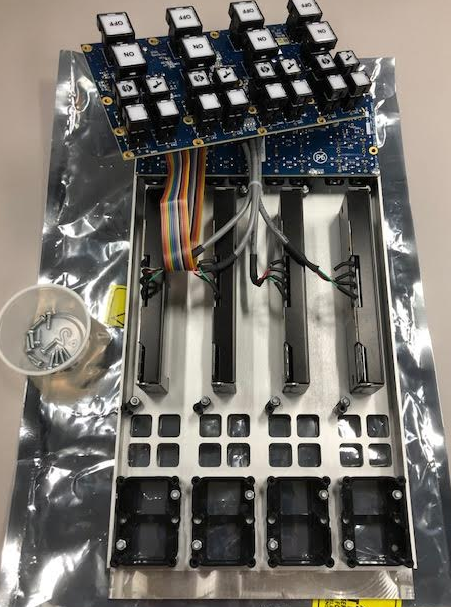
- Remove the two nuts holding the bezel to the module that needs to be replaced.
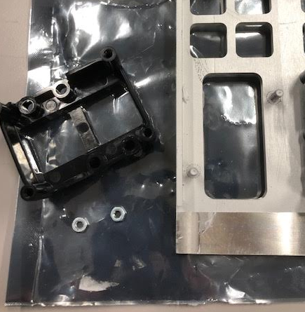
- Fit the new bezel onto the module and securely reattach the nuts.
- Reattached the bottom board with the 11 Phillips screws previously removed.
- Reconnect the CANbus and ribbon cables and reinstall the module into the console.
Let us know how we can help
If you have further questions on this topic or have ideas about improving this document, please contact us.