Setting up an On-Air light
 Updated
by
Bryan Jones
Updated
by
Bryan Jones
Scope
This article covers the setup of an On-Air light for the following Consoles:
- iQ series consoles - This includes iQ, iQx, Radius, RAQ, and DESQ.
- Fusion and Element consoles
- Quasar consoles
Description
The On-Air lights for all consoles function the same way. Although the setup menus differ slightly, all consoles have separate controls for the Control Room and Studio On-Air lights.
The On-Air lights follow the muting state of each room. That is to say, any time the Control Room monitors mute, the On-Air lights turn on. Similarly, when the Studio monitors mute, the Studio On-Air lights are on.
Speaker muting happens automatically. Microphones in the Control Room will mute the Control Room monitor speakers. These include the following microphone types;
- Operator
- CR Producer
- CR Guest
Microphones in the Studio will mute the Studio speakers. This consists of the following microphone type;
- Studio Guest
Using this method eliminates the need for complicated wiring or other configurations when there are multiple microphones in each studio.
CONFIGURATION
You configure the logic ports used for Control Room and Studio On-Air lights in the SHOW profiles of the consoles.
iQ SERIES
This procedure is the same for the iQ, IQx, Radius, RAQ, and DESQ consoles.
- Using a Web browser, log in to the configuration page of your console.
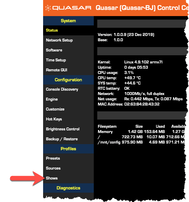
- Click on the Shows link located under Profile Manager on the left side menu.
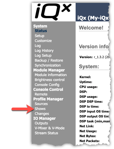
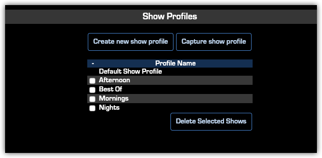
A list showing the four Profiles available is displayed.
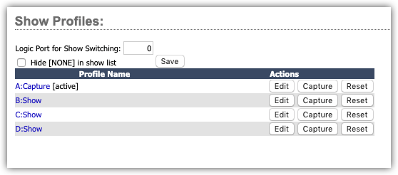
- Click on the name of the show you want to edit.
In the Profile, locate the Monitor Section heading. We are primarily concerned with CR Monitor and Studio Monitor columns and the Logic port for each. If you do not have a separate Studio, you do not need to configure the Logic port for the Studio Monitor.
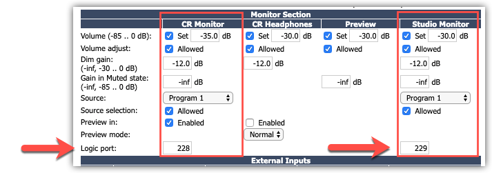
- Enter an UNUSED Livewire channel in the Logic port for both the CR Monitor and Studio Monitor sections.
- Click the Save button at the bottom of the page.
- Repeat this for any other Show Profiles
FUSION AND ELEMENT
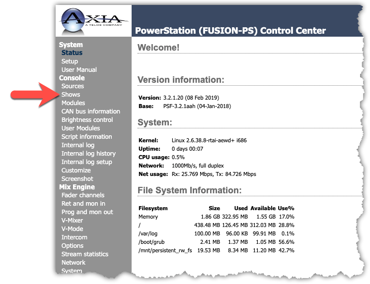
- Using a Web browser, log in to the configuration page of your console.
- Click on the Shows link located under Console on the left side menu.
A list showing the four Profiles available is displayed.
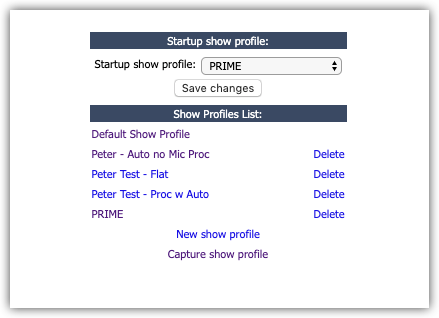
- Click on the name of the show you want to edit.
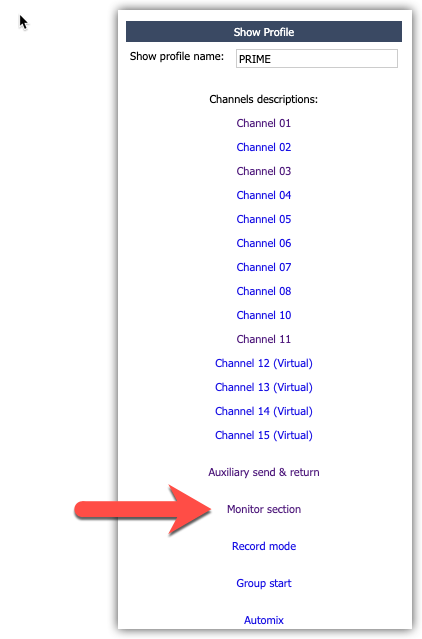
- Click on the Monitor section link.
- Scroll down and locate the section called Control Room Monitor Options.
- Enter an UNUSED Livewire channel in the GPIO channel for CR Monitor box.
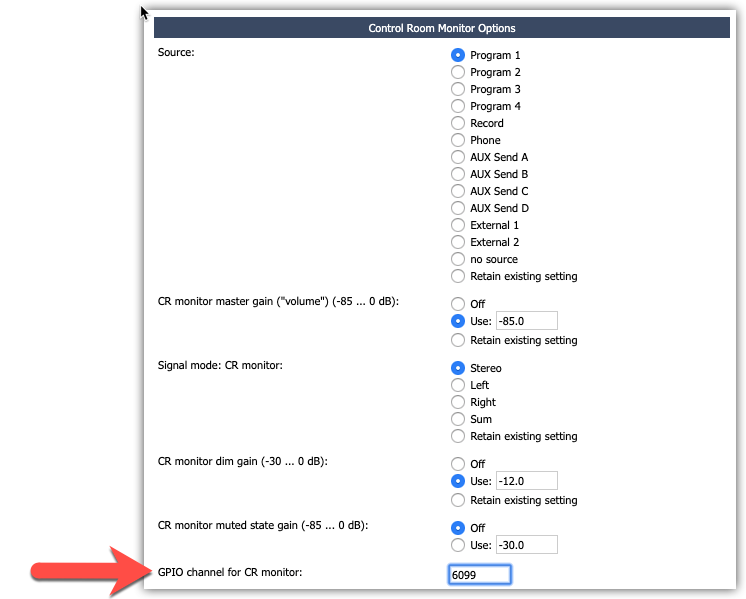
- Repeat this step for the Studio Monitor Options section. If you do not use a separate studio, you can skip this step.
- Save your Show Profile settings.
QUASAR
- Using a Web browser, log in to the configuration page of your console.
- Click on the Shows link located under Profile Manager on the left side menu.
A list showing all Profiles is displayed.
- Click on the name of the show you want to edit.
- Click on the Monitor Section button.
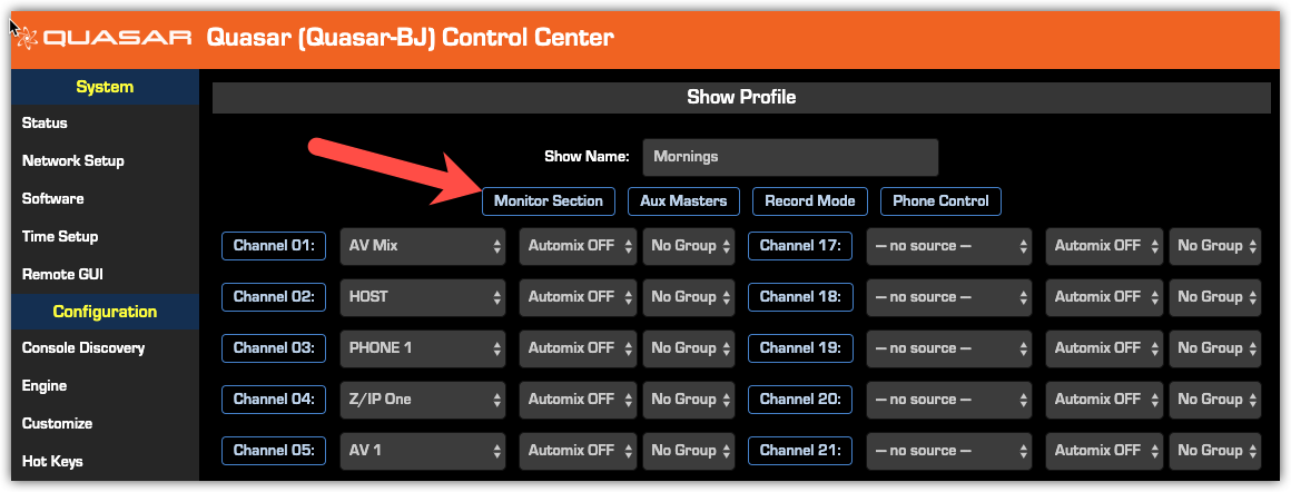
In the Profile, locate the Monitor Section heading. We are primarily concerned with CR Monitor and Studio Monitor columns and the Logic port for each. If you do not have a separate Studio, you do not need to configure the Logic port for the Studio Monitor.
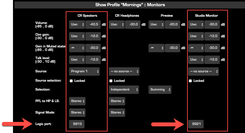
- Enter an UNUSED Livewire channel in the Logic port for both the CR Monitor and Studio Monitor sections.
- Click the Save Show button at the bottom of the page.
- Repeat this for any other Show Profiles
CONFIGURING THE GPIO NODE
- Using a Web browser, log in to the configuration page of your GPIO node.
GPIO ports on PowerStation, QOR, xNode, etc, can can all be used for controlling on air light.
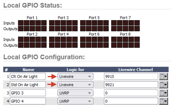
- Enter the channel you specified in your Show profile into the Channel field of your GPIO node
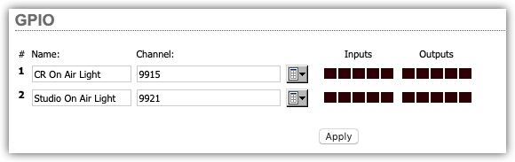
- Click Apply
IF USING GPIO PORTS ON THE QOR ENGINE
Ensure that the "Logic for" drop down is set to Livewire for the GPIO ports being used with the Control Room or Studio Logic channel