Enabling the virtual GPIO node in Pathfinder Core Pro
 Updated
by
Bryan Jones
Updated
by
Bryan Jones
Scope
Recent versions of Pathfinder Core Pro have a virtual GPIO node that can be enabled to mimic a physical (wired) GPIO node. This document covers enabling the basic GPIO node. Specific applications are covered in separate topics.
Description
For many years the basics of control have centered around GPIO. GPIO used with Pathfinder allows devices that might otherwise have only basic GPIO functions to perform a limitless number of tasks. The challenge has always been finding enough GPIO to configure these tasks.
Pathfinder Core Pro's Virtual GPIO (one enabled) functions exactly like a physical GPIO port you would find on a Node or Console Engines like a PowerStation or QOR.
Enabling GPIO in Pathfinder Core Pro
- Log in to the main Web Page of your Pathfinder Core Pro
- On the left side menu, click the GPIO page link found under the System settings.
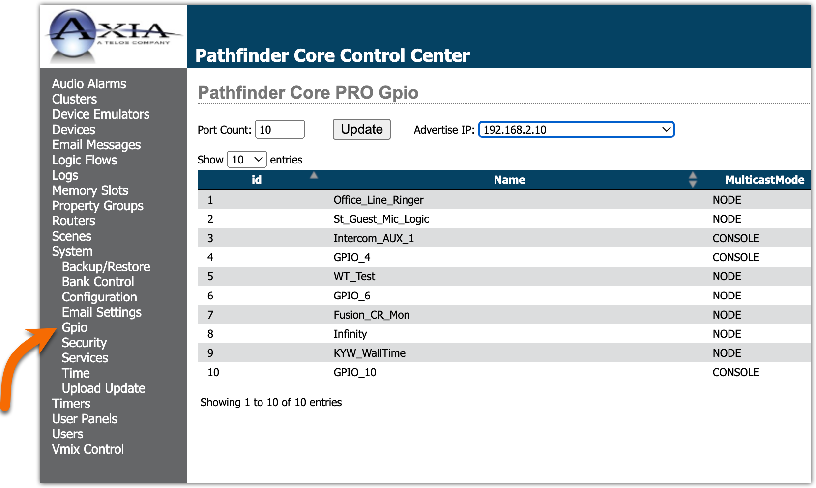
- Set the Port Count and click the Update button
- Some devices require GPIO advertisement (for example, Telos Infinity intercoms). Pick the IP Address to use for Advertisement. If you are unsure, leave this set to None. You can always come back and enable it later.
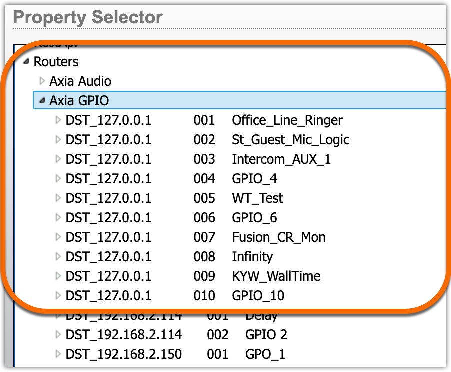
Your GPIO node can now be used as you would use ANY GPIO node.
It appears under Routers in the Property selector with a localhost (127.0.0.1) IP Address.
Basic GPIO configuration
- Click the Edit link to the far right of one of your newly created GPIO ports
- Leaving all other options the same, (note, default options are shown here) you can specify either a GPIO channel number or an IPaddress/port number in the Source Address box
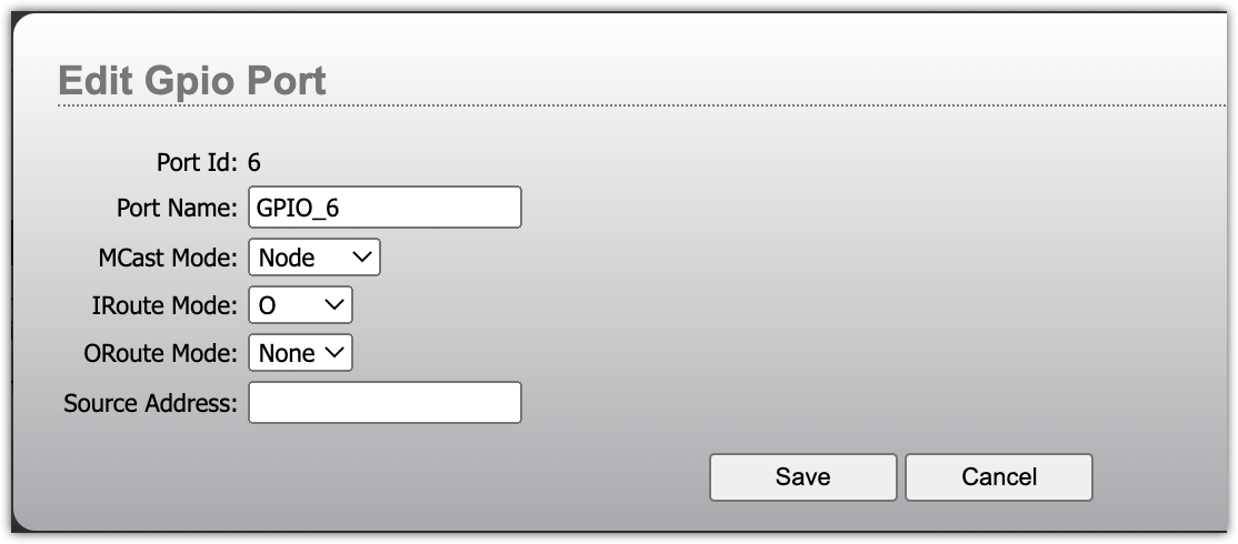
- Change the Port Name to something more descriptive.
- Click Save
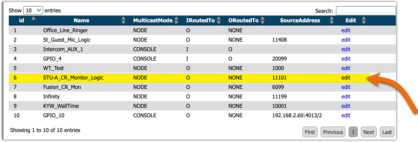
In this example, we changed the Port Name to STU-A CR Monitor Logic and set the source address to 11101 (the same channel configured in the Console's Show profile).
Let us know how we can help
If you have further questions on this topic or have ideas about improving this document, please contact us.