Creating Custom Machine Start logic in Pathfinder Core PRO
 Updated
by
Bryan Jones
Updated
by
Bryan Jones
Scope
This document describes Pathfinder Core PRO's use to create custom machine control logic from your Axia console to a GPIO port. The specific console doesn't matter as they all function the same.
Description
Most GPIO works by simply assigning the Livewire channel of the source on your console to the GPIO port on a GPIO node. This creates a one-to-one fader to GPIO port configuration where all pins are pre-defined.
If you desire a scenario where one GPIO port controls many devices, use Pathfinder Core PRO to assign just the logic you want to the pins you need.
In this example;
- There are two CD players. For discussion purposes, CD1 is Livewire channel 3901, and CD2 is Livewire channel 3902.
- There is a single GPIO port;
- Output Pin 1 starts CD1
- Output Pin 2 stops CD1
- Output Pin 3 starts CD2
- Output Pin 4 stops CD2
Configuring Pathfinder
- From the main Pathfinder web page, click on Logic Flows on the left side menu.
- Expand the Logic Flows folder tree from the right side, and select a folder (or create a new one) where the Logic Flow will be stored.
- Click the Green + (add new) icon at the top of the Pathfinder logic flow screen.
- Double-click on the Input block to the left of the Translator block
- Locate the Console group folder and click the arrow to expand it.
- Locate the console where the CD is configured and click the arrow to expand it.
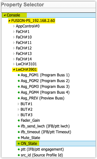
- Scroll down past the FaCH (Fader Channels) and locate LwCH#3901 (the first CD player) and expand it.
- Locate the On_State property (it will have a green dot to the left) and click to select it.
- Click the Select Button.
- Double-click on the Output block to the right of the Translator Block
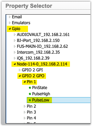
- Locate the GPIO group folder and click the arrow to expand it.
- Locate the GPIO "NODE" where your CD player is wired and expand it
- Locate the GPIO "PORT" where your CD player is wired and expand it. (Make sure to select GPO and not GPI)
- Locate the first Pin where the ON for CD 1 is wired and expand it.
- Locate PulseLow (it will have a green dot to the left) and select it.
- Click Select
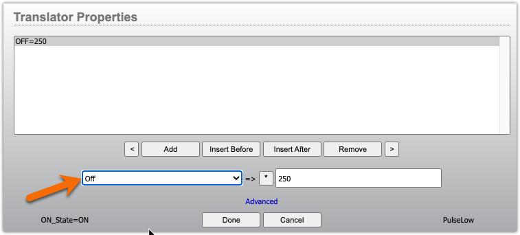
- Double-click on the Translator Block
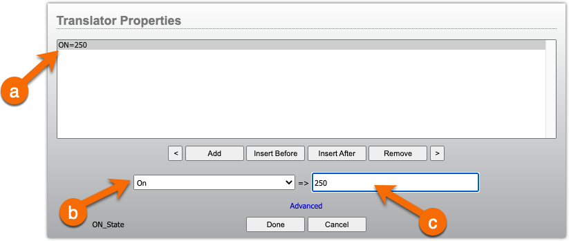
- Click to select the *=* entry in the Properties window.
- From the pulldown list, select ON for the ON_State property.
- In the text box to the left, enter a pulse time (in milliseconds). In this example, we'll use 250.
- Click Done
- Click Apply at the top of the Logic Flow page to save your work.
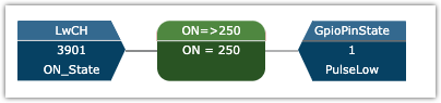
You now have a completed Logic flow that gives you a 250ms pulse on output pin 1 when the channel turns ON.
Complete these steps for the remaining pins
You will repeat these steps for the remaining pins.
Note that there is no OFF_State like we have for ON. So you might ask, how do I get a pulse when the channel turns off? Technically, you don't. Your next logic flow for the STOP pulse will be created by a NOT ON, ON_State.
For CD1 Stop, you are going to repeat ALL OF STEP 4 again exactly as shown. Then repeat ALL OF STEP 5 again but pick Pin 2, PulseLow (for the Stop pin). However, in STEP 6, pick OFF from the pulldown list (instead of ON). Like this;
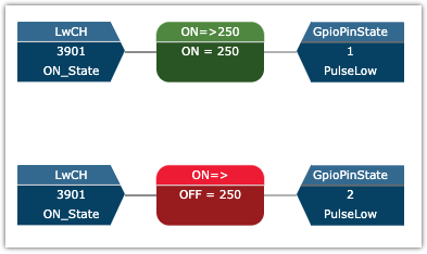
When you are done with CD1, you should have two logic flows that look similar to this.
Let us know how we can help
If you have further questions on this topic or have ideas about improving this document, please contact us.