Using Axia GPIO to control Z/IPStream R2 Metadata
 Updated
by
Bryan Jones
Updated
by
Bryan Jones
Scope
The Metadata2 server built-in to the Z/IPStream R/2 can accept GPIO events from an Axia GPIO node. The Metadata Server can use these GPIO events to enable or disable other blocks or send custom metadata messages. The sections below cover these topics in more detail.
Accepting Axia GPIO
The Metadata2 server reads GPIO by connecting to a GPIO device and reading the GPIO events. Follow these steps to create a GPIO source block:
- Open the Metadata2UI application and connect to the R2 you need to configure.
- From the “Sources” menu, select “Connect to remote system over TCP”. The following dialog will be displayed:
- Fill out the Source information
- Enter a display name, for example, “Axia1”
- Enter the connection IP address and port number. Almost all Axia GPIO use port 93 to communicate GPIO events. For instance, if the GPIO node’s IP address is “192.168.1.89”, you would enter “192.168.1.89:93” as the connection address.
- In the “Filter” field, select “Axia GPIO”
- Leave the “Code page” field as “<default>”
- Click the “OK” button.
Reacting to Axia GPIO events
Axia GPIO has some number of GPIO ports (usually six or eight, depending on the product but could be more in the case of the IP Driver or Pathfinder Core). Each port offers five GPI and five GPO pins. The state of each port is reported as a five-character string representing the five individual pins.
A word about pin states
- A pin in an “open” state is reported using the lowercase letter ‘h’
- A pin changing to an open state is reported using the uppercase letter ‘H’
- A pin in a “closed” state is reported using the lowercase letter ‘l’
- A pin changing to a "closed" state is reported using the uppercase letter ‘L’
- The initial response at the time the pin changes state is with the capital letter in upper case; otherwise, pins are reported with a lowercase letter.
When the server reads an event from an Axia GPIO, it generates a port/pin state metadata packet. This metadata packet will contain fields named “gpi1,” “gpi2,” and so on, up to the maximum port number for the device being monitored. Each field value will consist of the five-character string representing the pin states for the port.
For example, if pin one on port three was just closed, while the other pins are open, the value of the “gpi3” field will be “Lhhhh”.
If GPO events are available, they are stored in fields named “gpo1," “gpo2,” etc. with similar pin state strings.
Using Control Blocks
We will use “Control” blocks to examine and react to GPIO messages. The sections below describe this in more detail. You can think of Control Blocks like a button that gets pressed by whatever the conditions are (in our example GPIO).
Enabling or disabling other metadata components
In this section, we’ll assume that you have two external metadata sources, “Src1” and “Src2”, (maybe these are two different radio automation systems), and we want to switch between them in response to button presses. The metadata block diagram of our setup looks like this:
These new Control Blocks are controlled by two external momentary buttons. Button-1, wired to port three, GPI pin one, when pressed, will select “Src1” as the metadata source. Button-2, wired to port four, GPI pin one, will select “Src2” when pressed.
Follow these steps to create and configure the Control Blocks:
- From the Metadata2ui application, connect to the R2 you want to configure
- Select “Control” from the “Converters” menu. The following dialog will be displayed:
- Complete the control block information
- Enter a short display name (“control 1”)
- Select the Axia GPIO source from the “Source” drop-down list that we created in the first section
- In the “Match code” field, enter: (NOTE: there are double equal signs)
gpi3==”Lhhhh” - Select “Lua expression” from the drop-down list.
- In the “Actions” field enter:
enable “Src1”
  disable “Src2”
(NOTE: what's in the quotes needs to match the name of the Source you created) - The completed control looks like this
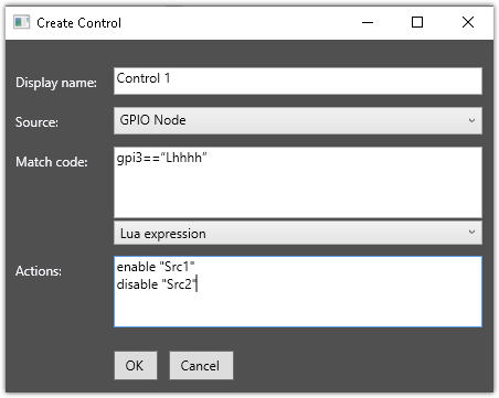
- Click OK when done.
- Repeat the steps above to create “control 2” but use
gpi4==”Lhhhh”anddisable “Src1”andenable “Src2”as the action.
We're now done. When button one is pressed, "Src1" will be enabled, and "Src2" will be disabled. When button two is pressed, "Src1" will be disabled, and "Src2" will be enabled.
Sending custom metadata on GPIO events
Sometimes, you may want to send custom metadata messages instead of switching sources (or you could do both). In this example, we will send different metadata messages in response to the buttons described in the previous section. The block diagram now looks like this:
- Follow steps one through four of the prior section, but leave the "Actions" field blank
We’re going to create two new translator blocks and "attach" them to “control 1” and “control 2”. Each translator block will add the metadata fields we want to send when the respective button is pressed.
- From the Converters menu in Metadata2UI, select Translator. A blank Translator block will open.
- Enter a Display name. Enter something descriptive, like "Control 1 Translator"
- Pick the Control Block you created in the previous step for Source:
- Add some rules to your translator.
The finished Translator block looks like this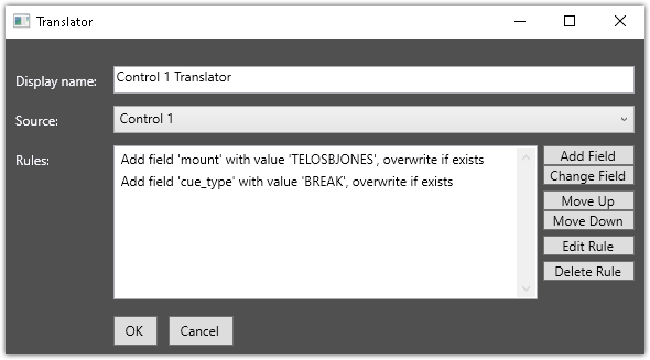
- Click OK when done.
- Repeat these steps for Control 2, and instead of sending cue_type of BREAK, change your rule so that cue_type sends ENDBREAK.
Final Steps
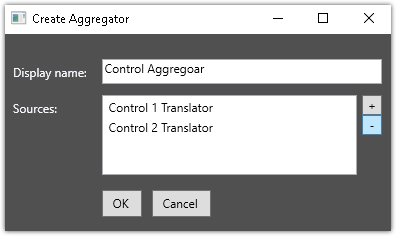
If you added more than one translator, you will need to add an Aggregator from the Converters menu. In our example we created two Translators and an Aggregaor is required to combine the outputs from the Control 1 Translator and the Control 2 Translator. Here is an example of what that Aggregator might look like.
Let us know how we can help
If you have further questions on this topic or have ideas about improving this document, please contact us.