Configuring Cisco Catalyst 1000 Series Switches for Livewire
 Updated
by
Bryan Jones
Updated
by
Bryan Jones
Scope
This document covers the configuration of the Cisco 1000 series of switches for use with a Livewire+ network. Testing and setup based on Cisco IOS Software, C1000 Software (C1000-UNIVERSALK9-M), Version 15.2(7)E4, RELEASE SOFTWARE.
Introduction
We don't intend for this to be a complete or step-by-step manual on how to configure your Switch. It is provided as a guide and makes some underlying assumptions regarding the skill level of the person doing the programming. If you are not comfortable hooking up serial cables, assigning IP addresses, typing in command line interfaces, etc., you should contact your IT department for assistance.
If this is the first time configuration, you will have to connect to the Switch via a console cable and serial connection to enter into setup. After the initial configuration, you can connect to the Switch via a Telnet session or through a serial port.
Connect to this switch using a USB cable and a serial port driver from Cisco, or connect using a standard Cisco "console" cable.
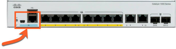
As of this writing, the Windows USB driver can be obtained from the Cisco website. Make sure you install the driver before connecting the switch to your USB ports. Installing the driver and connecting the cable will install a new COM port on your computer. Use the device manager for your operating system to determine what COM port has been installed. PuTTy is a free terminal program that can be used for configuration and can be downloaded here.
Programming
Once connected with the serial cable (default settings are 9600 baud), you will see messages on the screen as the switch boots. Seeing these messages confirms that your serial cable is working correctly. If prompted to enter any setup wizards, please answer ‘No.’
A couple of other notes that might be helpful:
- Many commands can be abbreviated and just need to be unambiguous. For example, the
enablecommand is often abbreviated asenandconfigure terminalis often abbreviated asconfig t. All commands can be abbreviated. - The TAB key completes a word and checks it for correctness. For example, if you type ‘en’ and then press TAB it will spell out the word ‘enable’.
- The
#(pound or hash sign) indicates you are in privileged mode. For example, if your prompt saysSwitch>and you try to typeconfig t, you will receive an error because you are not in privileged mode. Typing theenablecommand will give you theSwitch#prompt indicating the privileged mode.
Set the passwords
We suggest using a password of ‘Livewire’ or some other password that is easy to remember.
Switch>enable
Switch#configure terminal
Switch(config)#username AAAA password Livewire
Switch(config)#enable password Axia
Set the hostname
We suggest setting the hostname of each switch to something descriptive. Suggestions might be AXIACORE01, or AXIAEDGE01, etc. In this example, we will use AXIA01.
To change the hostname from the default of ‘Switch’, type the following from the prompt;
Switch(config)#hostname AXIA01
AXIA01(config)#
Assigning an IP address to Vlan 1
By default, Livewire uses Vlan 1. It is possible to use other Vlans; however, support for that is outside of the scope of this document. Please contact your Cisco dealer, Cisco support, or your IT Group for assistance on using other Vlans.
To set the IP address, type the following from the prompt (replace the IP address shown with one appropriate to your configuration):
AXIA01>enable
AXIA01#config terminal
AXIA01(config)#interface vlan1
AXIA01(config-if)#ip address 192.168.2.2 255.255.255.0
AXIA01(config-if)#no shutdown
AXIA01(config-if)#end
Let’s save our configuration:
AXIA01#wr
Building configuration...
[OK]
AXIA01#
Allow access from Telnet
Again we suggest the use of a password that is easy to remember. In this case, “telnet123” is used as the password.
AXIA01#configure terminal
AXIA01(config)#line vty 0 15
AXIA01(config-line)#password telnet123
AXIA01(config-line)#login
AXIA01(config-line)#exit
Configuring Global QoS
AXIA01(config)#mls qos srr-queue output cos-map queue 1 threshold 1 6 7
AXIA01(config)#mls qos srr-queue output cos-map queue 2 threshold 1 5
AXIA01(config)#mls qos srr-queue output cos-map queue 3 threshold 1 0 1
AXIA01(config)#mls qos srr-queue output dscp-map queue 1 threshold 1 48
AXIA01(config)#mls qos srr-queue output dscp-map queue 2 threshold 1 46 34
AXIA01(config)#mls qos srr-queue output dscp-map queue 3 threshold 1 0
AXIA01(config)#mls qos
AXIA01(config)#end
AXIA01#wr
Building configuration...
[OK]
AXIA01#
Setup IGMP
AXIA01#config terminal
AXIA01(config)#ip igmp snooping querier
AXIA01(config)#ip igmp snooping vlan 1 immediate-leave
AXIA01(config)#ip igmp snooping querier max-response-time 25
AXIA01(config)#ip igmp snooping querier timer expiry 205
AXIA01(config)#end
To disable ip igmp querier on a Cisco switch use:
AXIA01#config terminal
AXIA01(config)#no ip igmp snooping querier
AXIA01(config)#end
Configuring Axia Device Ports (Access Ports)
Access ports are used for connecting “end point” devices like Axia nodes, engines, computers, as well as any other devices that are not considered “switches” (see note in trunk port configuration section).
To configure multiple access ports at once, type the following from the prompt:
AXIA01#config terminal
AXIA01(config)#interface range GigabitEthernet1/0/1 - 22
AXIA01(config-if-range)#switchport mode access
AXIA01(config-if-range)#switchport nonegotiate
AXIA01(config-if-range)#switchport voice vlan dot1p
AXIA01(config-if-range)#priority-queue out
AXIA01(config-if-range)#no power efficient-ethernet auto
AXIA01(config-if-range)#mls qos trust dscp *SEE NOTE BELOW*
AXIA01(config-if-range)#spanning-tree portfast
AXIA01(config-if-range)#no ip igmp snooping tcn flood
AXIA01(config-if-range)#end
Configuring Trunk Ports
Trunk ports are used for connecting other Cisco switches or Axia devices with switches built-in (like a PowerStation Main or QOR or xSwitch). Please note that when connecting to a PowerStation Main, only the GIG ports can be used, and they must be properly configured for Trunk operation in the Ethernet Switch configuration of the Element Control Center. QOR based devices and xSwitch should only be connected to the GIG Ports.
To configure multiple trunk ports at once, type the following from the prompt:
AXIA01#config t
AXIA01(config)#interface range GigabitEthernet1/0/23 - 24
AXIA01(config-if-range)#switchport mode trunk
AXIA01(config-if-range)#switchport trunk allowed vlan 1
AXIA01(config-if-range)#priority-queue out
AXIA01(config-if-range)#mls qos trust dscp
AXIA01(config-if-range)#no ip igmp snooping tcn flood
AXIA01(config-if-range)#no power efficient-ethernet auto
AXIA01(config-if-range)#end
Set Spanning-Tree settings
It’s important for your core switch to be set up as the master for the Spanning Tree protocol. If this switch will be the core switch for your Axia network then set it as the Spanning Tree root.
AXIA01#config t
AXIA01(config)#spanning-tree vlan 1 root primary
AXIA01(config)#end
Save and Check Your Work
To save your work type the following;
AXIA01#copy running-config startup-config
You will be prompted for a file name. Just press enter.
Destination filename [startup-config]?
Building configuration...
[OK]
AXIA01#
To check your work, from the command prompt, type;
AXIA01#show run
Use the spacebar to proceed a page at a time and double check your configuration.
Let us know how we can help
If you have further questions on this topic or have ideas about improving this document please contact us