QOR Engine Advanced GPIO
Combining multiple studio tallies on one port
There might be a moment in time, probably while you’re wiring up your mic tallies when you’ll ask yourself, “Do I really need to burn up one GPIO port for each and every studio talley?” Normally, yes. Each studio gets its own GPIO port because each port can serve multiple functions other than talley. If all you want to do is have tallies appear on a single port and you have QoR engines, this is the tech tip for you!
Step 1
Set up CR Monitor Logic as usual
In the Fusion/Element Show profile, enter a memorable channel number into the GPIO CHANNEL FOR CR MONITOR field and click apply. In the QOR, this same field is found in the show profile labeled LOGIC FOR CR MONITOR. Go through each show profile and make this same edit, but remember to use a different channel number for each engine. Since GPIO channels don’t advertise, use memorable channels, or the LW channel number being used for PGM1 output since program outputs have no GPIO data. This will help you keep track of them since they won’t show up in the BROWSE list otherwise. In this example, we’ll use 1, 2, and 3 for our CR Monitor Logic on three different engines.
Step 2
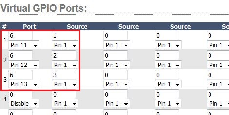
Configure the Virtual GPIO Port section of the QOR
Begin by choosing a NEW channel for the custom GPIO you are about to make. Remember that GPIO does not advertise, so you will want to pick one you’ll remember, but does not have any other GPIO on it. In this example, we’ll use "6". Enter this new channel into the PORT fields in the VIRTUAL GPIO PORTS section of the GPIO page in the QOR. Then set the drop-down boxes under the channel fields to the desired pins. In our example, pins 11, 12, and 13 are used. Then in the first SOURCE column, enter the channel numbers given to the show profiles earlier in the data fields and set the drop-down boxes to PIN 1, since we are looking for that closure on each of the individual ports. This might seem backward because it is. Stick with us here.
Step 3
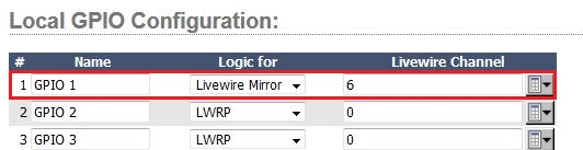
Configuring a Livewire Mirror GPIO Port
Go to the LOCAL GPIO CONFIGURATION section of the QOR’s GPIO page and select a port to use for your new custom GPIO configuration you just made. Enter the new channel number and set the LOGIC FOR drop-down box to LIVEWIRE MIRROR and click APPLY.
Livewire Mirror allows you mirror a logic port and show outputs where there are inputs. That’s why this might seem a little backwards. The virtual GPIO port and Livewire Mirror function are what allow this type of “hack.”
Now all you have to do is wire up your port and connect your tallies. In this configuration, the three control rooms will output tallies on output pins 1, 2, and 3.
Let us know how we can help
If you have further questions on this topic or have ideas about how we can improve this document, please contact us.