Modify PowerStation I/O Board to eliminate ESD Sensitivity resulting in Noise Level Increase on inputs
 Updated
by
Bryan Jones
Updated
by
Bryan Jones
Scope
This document covers modifications that can be made to Power Station Main and AUX I/O boards to eliminate sensitivity to ESD.
Description
Repeated ESD (static) strikes to the audio board (PCB 1401-00191-xxx) results in the noise floor being raised 20 to 30 dB. This can occur on any line or microphone input. The problem was simulated by 10 to 15 strikes of 5 to 15kV amplitude against the chassis. Energy would enter through Analog Output connector (J2) and raise the PCB copper potentials on the motherboard, desynchronizing the internal registers on the Input A/D converters, resulting in the increased noise floor. This behavior would continue until power was cycled. This rework addresses the entry mechanism.
This also requires knowledge of soldering and desoldering techniques and tools. If you are not comfortable with or do not have the skill to perform these modifications, please contact us for an RA to send your unit to us.
Modifications
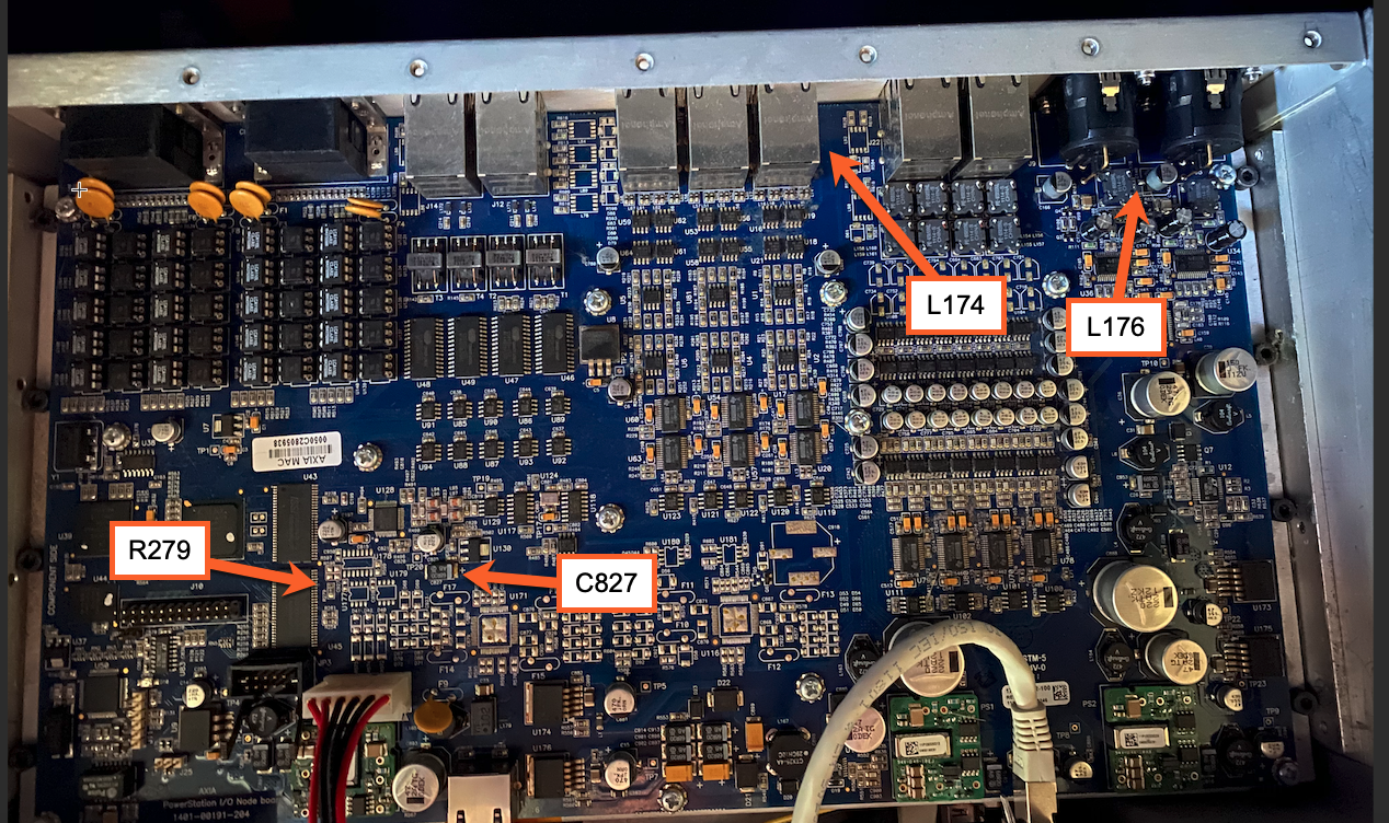
This picture shows the approximate locations of the components referenced in this document.
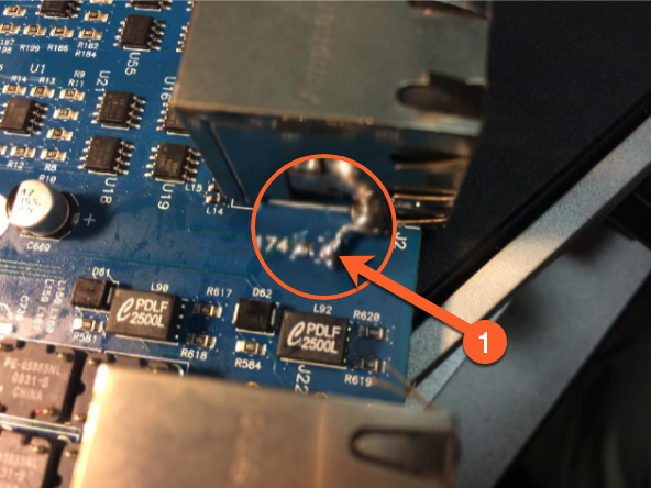
- Remove L174, add a wire jumper from the L174 pad nearest the PCB edge to the metal can of J2. Shown here in this image.
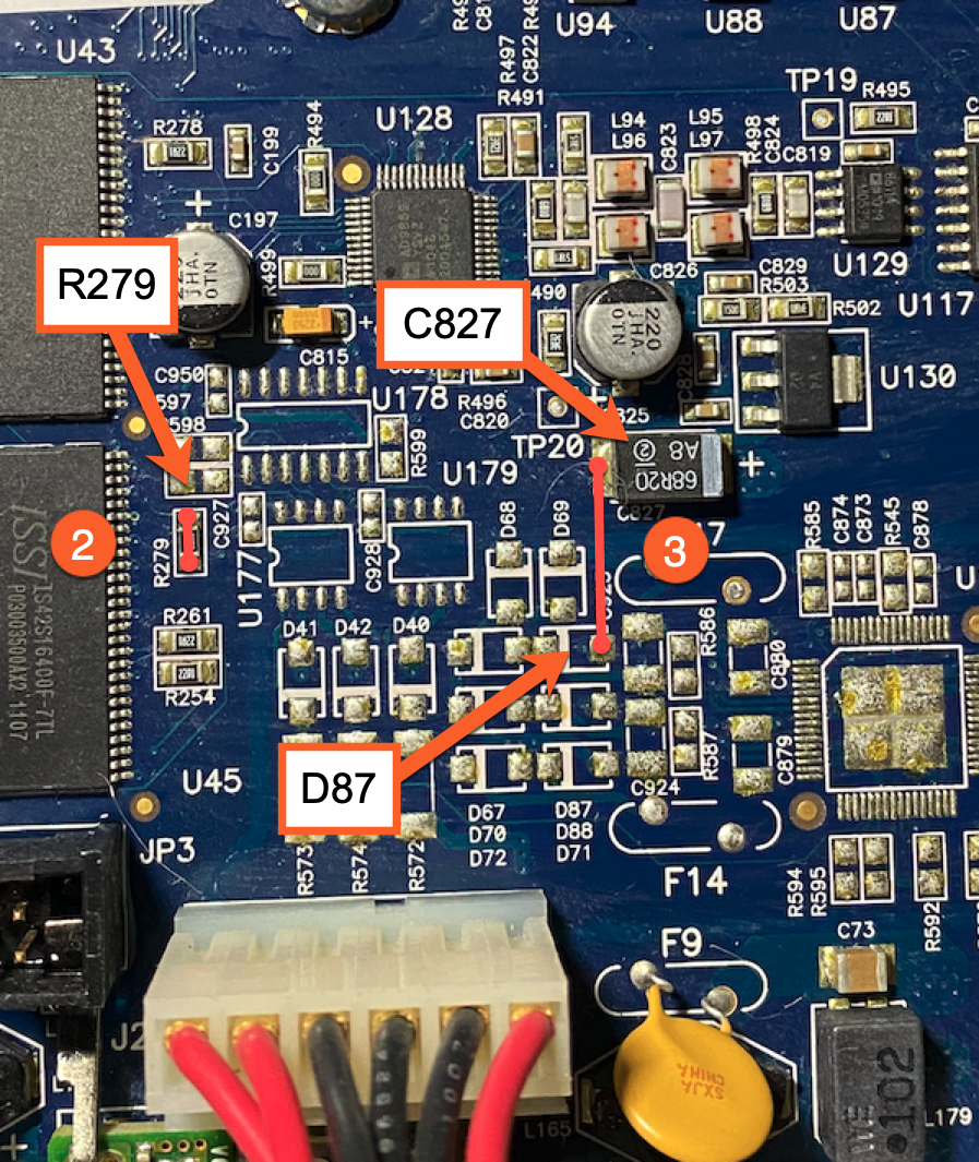
- Remove R279, add wire jumper across empty R279 location, shown below
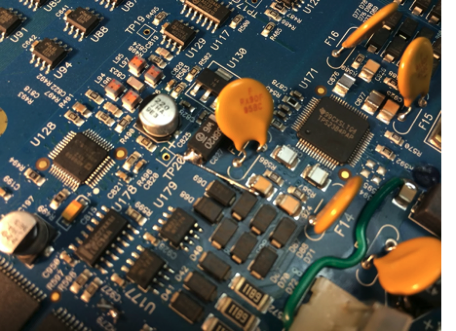
In the following steps, older boards will have components in some places. More recent boards will not. If your board HAS components installed, note that two of them can be removed as part of this rework.
- If D87 has a component installed, remove it and add a jumper from D87 location to C827 Cathode(-). If no diode, install the jumper as shown.
- Remove D67 as part of this rework.
This photo shows the same location on boards WITH the components installed.
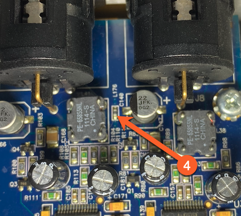
- Remove Ferrite L176, replace it with a jumper wire.
Let us know how we can help
If you have further questions on this topic or have ideas about how we can improve this document, please contact us.