Setting up System Timers in WallTime Clocks with Axia Consoles
 Updated
by
Bryan Jones
Updated
by
Bryan Jones
Scope
This document covers the configuration of the following console's use with a Paravel Systems WallTime
- Axia iQ Console
- Axia Radius Console
- Axia DesQ Console
- Axia RaQ Console
- Axia iQx AES67 console
As of this writing, WallTime is running version 3.0.6
Configuration
Configure your Console SHOW Profile.
- Using your Web browser, connect to the console where you want to configure the timer.
- Click on the Shows link on the menu down the left side of the page. You will be required to log in with your user name and password. The Show profiles will be displayed.
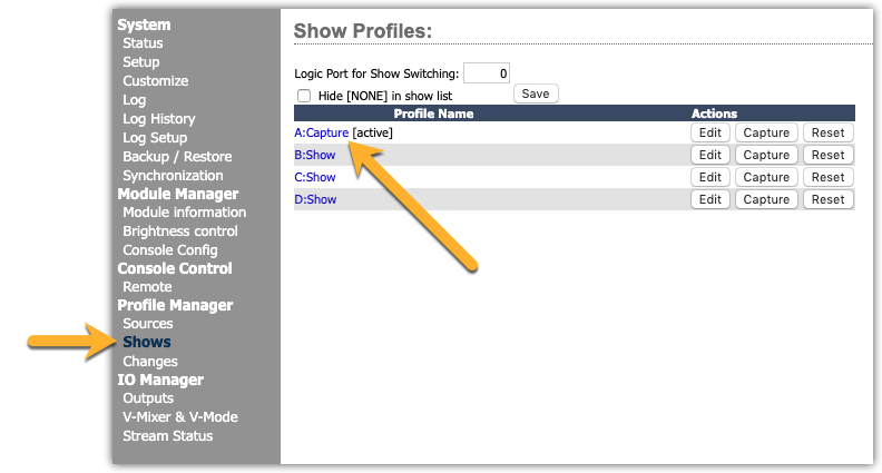
- On the Show Profile page, there are two settings to change.
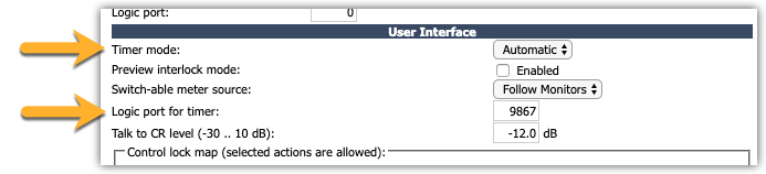
- Scroll down near the bottom of the page and locate the setting called "Timer Mode:" and set this to Automatic.
- In the "Logic port for timer:" option, supply any UNUSED Livewire channel. In this example, we will use 9867.
- Save the Show Profile and repeat this for any other Show Profiles needed. Note that you will need to re-load the show profile for the changes to take effect.
When we say to use an "unused" channel, we do this because, in any Livewire system, the Audio and GPIO travel on the same channel number. When using a channel loaded on a console, the timer would be incorrectly responding to the ON and OFF logic associated with the console.
Configure your Console SOURCE Profile.
- Click on the Sources link on the menu down the left side of the page.
- Select the Source where you want to enable the Timer to start.
- Scroll near the bottom of the page and locate the option that says "Auto-Start Timer" and click the Enable box.
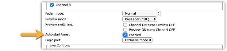
- Save your Source Profile settings.
- Repeat this for each Source that should start the timer. Note that Source Profiles will need to be re-loaded for changes to take effect.
Configure WallTime
Like Axia devices, you configure WallTime using your Web browser. For full details on configuration, we refer you to the WallTime site.
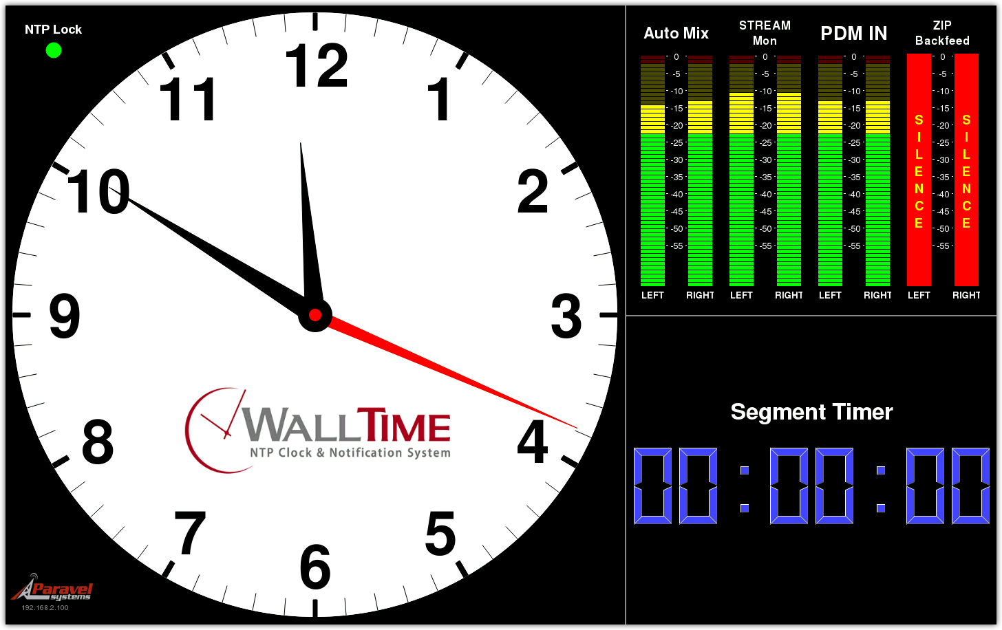
The IP Address of your WallTime is shown in the bottom left corner of the screen below the Paravel logo.

- Using your Web browser, log in to the configuration page for your WallTime. You will be required to supply a user name and password. By default, the user name is "user," and the password field is left blank.
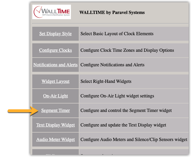
- Click on the Segment Timer link to Configure and control the Segment Timer widget.
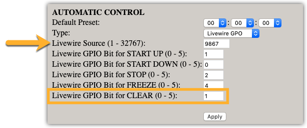
- On the Segment Timer configuration screen, select Livewire GPO from the drop-down list next to the Type: Setting.
- In the Livewire Sources box, enter the channel number we assigned in the first step. In this example, 9867.
- We need to make one change to the GPIO Bits. Leave all of the settings at their default, however, change the Livewire GPIO Bit for CLEAR (0 - 5): to 1
- Apply your changes.
Additional WallTime Information
In addition to this configuration, you must also configure your WallTime to display the Segment Timer. To do this, you will need to have your Display Style set to something that shows Widgets and then set either your Top or Bottom Widget options to show a segment timer. In this example, we have selected a Display Style of "Analog Clock with Widgets" and have the Bottom Widget set to Segment Timer. Here is an example of how the screen looks.
Some final notes about the Behavior
Configured the way we have it here, every fader that has Auto-reset enabled is going to reset the timer back to 00:00:00 (Zero). This means if you turn on your first Microphone, it starts the timer. The next fader to get turned on (that has auto-reset enabled) is also going to reset the timer.
One possible variation to this configuration would be to use the same logic that controls the On-Air light. This way, the timer resets when the monitors get muted. You would likely want to uncheck the enable option for Auto-reset. To do this, you would simply substitute the CR Monitor Logic port channel in place of 9867 that we used for Timer control. Leave the pins the same in the WallTime configuration. The pin that controls the on-air light is also pin 1.
Finally, for extra credit, you could also use Pathfinder to create the scenarios in which the timer is reset. For example, you could create a scenario where the first Mic that gets turned on resets the Segment Timer, but none of the other mics do. In this case, you would also want to turn OFF the auto-reset because Pathfinder is controlling that.
Let us know how we can help
If you have further questions on this topic or have ideas about how we can improve this document, please contact us.