Testing Powerstation IO Board
 Updated
by
Tony Dimsdale
Updated
by
Tony Dimsdale
Scope
The scope of this document is to test the IO board within the Powerstation Main or Aux units. You can use this document to test your analog in/outs GPIO connections internally to the Powerstation Main or Aux. For further issues with the Powerstations switch board or SOM engine portion. Please reach out to support directly.
Access via Serial Port or Telnet
A telnet session can be started, you will either receive a umon prompt or a login prompt. The telnet login is username = “user” and there is no password (unless one was set by the user). When the terminal shows a /umon> or /home> prompt , it’s ready to run the self-test.
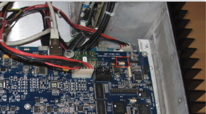
If using serial connection directly on the I/O board. Look for the 3 pin "J25" header. J25 Pin 1 to DB9 Pin 2. J25 Pin2 to DB9 Pin 5. J25 Pin 3 to DB9 Pin 3
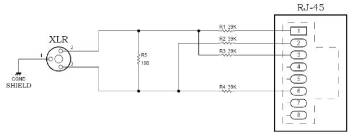
Mic Loopback Cables
For the self test, the microphone inputs will be plugged into the Powerstation’s analog outputs. A network of resistors is needed to match the level and impedance for the mic input. The Powerstation will need two (2) of these.
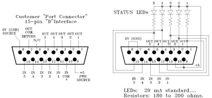
GPIO Loopback Tester
The self-test will check the operation of the GPIO port. LEDs are installed on the appliance so the technician can see failing or working outputs. Only one of these is needed as the program will test one port at a time.
Connect Loopback Cables
Before the test begins, the audio loopback test cables aforementioned need to be connected in this manner:
Microphone Input 1 ←→ Analog Output 1 Analog Input 3 ←→ Analog Output 5
Microphone input 2 ←→ Analog Output 2 Analog Input 4 ←→ Analog Output 6
Analog Input 1 ←→ Analog Output 3 AES/EBU Input 1 ←→ AES/EBU Output 1
Analog Input 2 ←→ Analog Output 4 AES/EBU Input 2 ←→ AES/EBU Output 2
Running the Test Application
The LWT test application is the self-test program that will verify the functionality of the interfaces. There is more information about the program at the end of this procedure. When ready, enter the following to execute the test mode program:
/home> LWTest -c
This command starts the test application. You’ll be greeted with a LWTest version number and an instruction to connect make sure loopback cables are connected and press Enter to continue.
RAM test:
Testing NVRam...
address: 0x0000 write: 0xBB read: 0xBB
address: 0x0020 write: 0x10 read: 0x10
address: 0x0040 write: 0x32 read: 0x32
… … (continues through address 0x03E0) … ...
PASS: NVRam passed
This is the first test in the sequence. Once this test completes, you’ll see a pass or fail. Pass means we can move on. Fail means one of the RAM chips might need changing. Contact Axia Support with a printout of the results from this test
GPIO Test
After this test, the terminal will ask you to plug in the GPIO tester. Pick one to start with and insert the tester into a DB connector and the GPIO test will run automatically. When one port is finished, it will tell you and you can move to the next and so on. You should see this by the time you’re done:
...
yyyyy yyyyy yyyyy yyyyy
Remove the tester from port 4
GPIO-ports Test success
And all of the LED’s should light in sequence on the tester for each port. If you see “N”, “F”, or missing LED’s on the tester, contact Axia Support with test results handy. If you see all LEDs working, all ‘Y’s and a success message, onward!
Audio I/O Tests:
The next portion of the self test is the audio port testing. It will check for noise floor, audio levels at different frequencies, gain reduction, and total harmonic distortion. There is no user input required and will terminate the test after it is finished. You’ll see the results of the audio tests echoed on the terminal and whether or not each portion of the test has passed or failed. A “failure” by a small margin is considered a pass. Common port failures in multiple portions suggests a problem with the output or the input circuitry. Contact Support with your test results.
Let us know how we can help
If you have further questions on this topic or have ideas about how we can improve this document, please contact us.