QOR Console - Channel OLED replacement
Scope
This document describes the process of determining the type of OLED panels present in the Radius, iQ, RAQ, and DESQ consoles' input channels and the replacement of such.
Before we begin
Disconnect all cabling and power from the unit prior to servicing. Please take the time to read through this document before starting any work. You will be exposing very sensitive components to the outside world, so please take special care to work in a static and moisture-free environment. Field upgrades and repairs are performed at your own risk, so please take care. If you would rather send the unit to the factory for service, contact Telos Technical Support and request a Return Authorization.
Old vs New OLEDs
There have been two types of OLEDs used throughout the course of the QOR console’s life. The new style OLEDs will not work with the older style ones, so you will want to know which style your console uses. If your console has the older style OLEDs or if you don’t know, you will want to order enough OLEDs to replace all of them. The part number for the 1”x 1” OLED is 1771-00119.
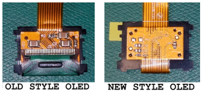
There are two ways to identify new or old OLEDs.
- Inspect the underside of the OLEDs themselves and compare them to the photos to the right.
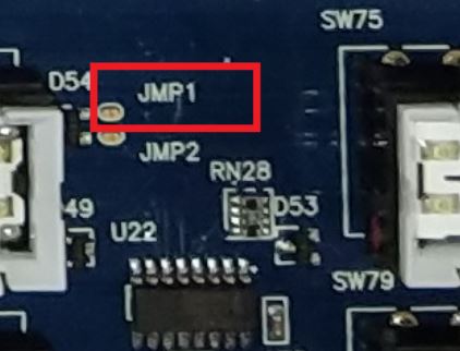
- Inspect JMP1*. If the jumper point JMP1* is bridged with solder, the console has new style OLEDs. We’ll talk about this on PG2.
Update Firmware
Consoles receiving new OLEDs must have their firmware updated to the latest version otherwise, they will not function properly. Please go to your QOR’s MODULE MANAGER > MODULE INFORMATION page and ensure that the surface is running firmware version 5.49 or newer. If the version is older than this, go to our website and download the newest firmware and follow the instructions in the product manual for updating the firmware. The firmware can be found under the SOFTWARE tab of the iQ page on our website here:
https://www.telosalliance.com/Axia/iQ
Console Disassembly
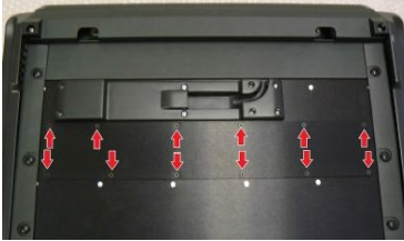
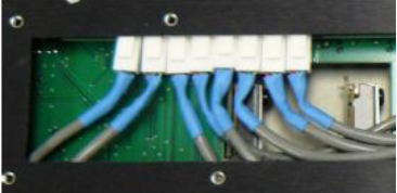
Carefully flip the console over and remove the 12 Philips screws holding the metal panel to the underside of the unit. Remove the panel to reveal the fader connections. They appear in sequence the same way the faders are oriented in the console. I.E. With the console upside down, Fader 1 is all the way to the right. Disconnect these cables from the CPU board. Be careful not to break the connectors or their connections to the board. Note the way the cables are routed through the openings in the front panel PCB. Making note of this now will help you later when reassembling the unit.
Remove Top Panel
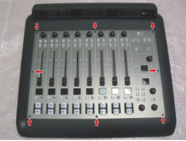
Once the fader cables have been disconnected, the top panel can be removed from the unit. Start by removing the 8 hex screws on the top panel. When these screws have been removed, the top panel will be free to come off the console. The faders will still be attached to the top panel, so be careful out-feeding the cables.
Removing the OLEDs
Start by carefully removing the OLED from the housing frame. Then locate the retaining tab in the ribbon cable connector on the PCB and lift to remove the ribbon. The OLED should now be free to remove and replace. Repeat with the remaining OLEDs.
In this first video, we show the process of removing the housing that mounts the OLED in the Console.
In this second video, we show you how to assemble the new OLED into the housing assembly.
Short JMP1* --see note--
Locate JMP1 on the board between channel 7 & 8’s ON/OFF buttons. Carefully bridge the two pads at location JMP1* with solder. Keep temperature and dwell time low but still assure a good connection. It’s important that the solder pads are not damaged during this process.
Test and Button up
Carefully connect the console in its current state to a QOR and power the system up. Ensure that the OLEDs are operating correctly and power everything back down. Now, reverse the disassembly instructions to put everything back together.
After performing the replacement, if the image on the display seems distorted, upside-down, and backward, check one of the following two things:
- Firmware version running in the Console. Remember, 5.49 or newer needs to be installed
- JMP1*, remember that a short at JMP1* tells the firmware to send the correct data for the new OLEDs.
If difficulties are experienced during this procedure or if this procedure seems too involved for field service, let us know. We can issue an RA and you can send the console to us for this work.
For changing the OLEDs in the iQ’s overbridge, contact Axia Support for more information and for parts availability. There are older and newer style OLEDs for the overbridge modules as well, so you’ll want to make sure you order the correct hardware for your needs.
Let us know how we can help
If you have further questions on this topic or have ideas about improving this document, please contact us.