QOR Console - Meter OLED Replacement
Before we begin
Disconnect all cabling and power from the unit prior to servicing. Please take the time to read through this document before starting any work so that everything is understood before proceeding. You will be exposing very sensitive components to the outside world, so please take special care to work in a static and moisture free environment. Field upgrades and repairs are performed at your own risk, so please take care. If you would rather send the unit in to the factory for service, contact Telos Technical Support and request a Return Authorization. Instructions for replacing the channel OLEDs are also available by request.
Old vs New OLEDs
The iQ has two different types of 2.7” OLED’s depending on the age of the unit. To determine which OLED types are in the unit, remove the lens to see which 1401-XXXXX number is stenciled on the overbridge pcb or read the CPU board revision number (see page 2)
- 1701-00361 (newer) uses 1401- 00297 pcb with 1171-00056 2.7" OLED [30 pins]
- 1701-00268 (older) uses 1401- 00219 pcb with 1171-00031 2.7" OLED [34 pins]
The reason for this change is the original OLEDs can no longer be produced. Since they are no longer available, we are not able to replace just the OLED on older consoles. Instead, we will have to replace the OLEDs and the display board. See page 2 to see how to determine what you need to order from us.
Update Firmware
Consoles receiving new OLEDs must have their firmware updated to the latest version, otherwise they will not function properly. Please go to your QOR’s MODULE MANAGER > MODULE INFORMATION page and ensure that the surface is running firmware version 5.49 or newer. If the version is older than this, go to our website and download the newest firmware and follow the instructions in the product manual for updating the firmware. The firmware can be found under the SOFTWARE tab of the iQ page on our website here:
https://www.telosalliance.com/Axia/iQ
Determining type based on CPU revision:
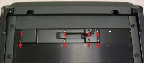
On the under side of the console, remove the 12 Phillips screws holding the inspection panel in place. The 4 round-head screws do not require removal.
Next to the last fader connection, the board reads “CO
BALT SURFACE MAIN BOARD.” Below this is the board number:
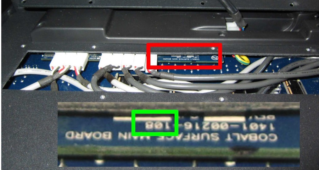
● 1401-00216- 108: This console has the older style OLEDs in the overbridge. The display PCB and OLEDs will need changing in this case. Order overbridge display board 1701-00268
● 1401-00216- 110 (or higher): This console has a newer style display board installed. These OLEDs can be changed without ordering a new PCB.
Overbridge Disassembly Instructions:
Tools:
- #1 Phillips screwdriver
- #2 Phillips screwdriver
- 5mm hex key
Start by removing the 8 screws securing the plastic CANBUS hood:
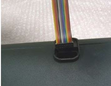
Remove the hood and locate the ribbon cable connecting the meter bridge to the CPU. Unseat the cable. The cable will be trapped between the chassis and the frame.
Locate and remove the two 5mm hex screws connecting the meter bridge assembly to the frame.
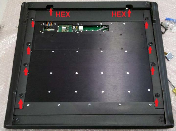
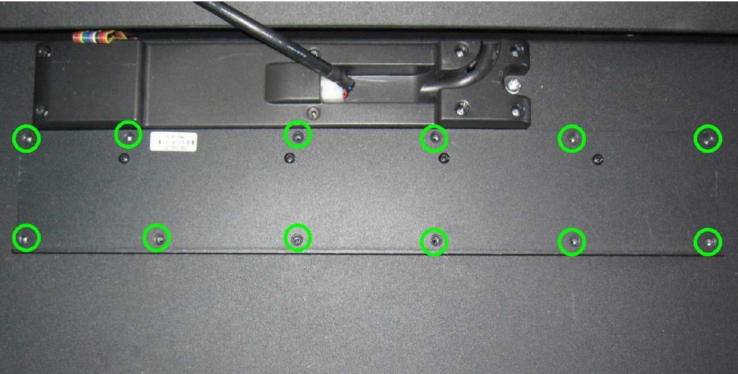
Next, remove the top 6 screws holding the chassis to the frame and loosen the bottom two. This will allow the mixer chassis to drop away from the frame, allowing the ribbon cable to be passed through the access hole in the frame. The chassis does not need to be removed completely, just moved out of the way enough to allow you to remove the ribbon cable.
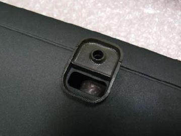
At this point, you should be able to separate the meterbridge assembly from the console. Move the meterbridge assembly to a fresh workspace for further disassembly. Make note of where the spacers are located between the meterbridge and the console frame. These will need to go back in place during reassembly:
Looking straight on with the meterbridge correct side up, use a #1 philips screwdriver to remove the RIGHT endcap bezel (2 screws) and continue by removing the inner endcap by removing four screws with a #2 phillips screwdriver.
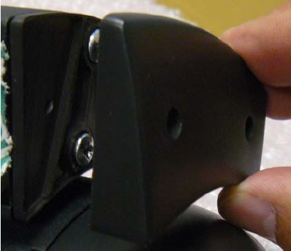
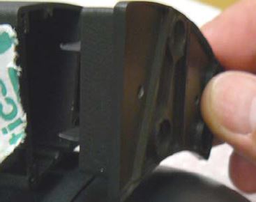
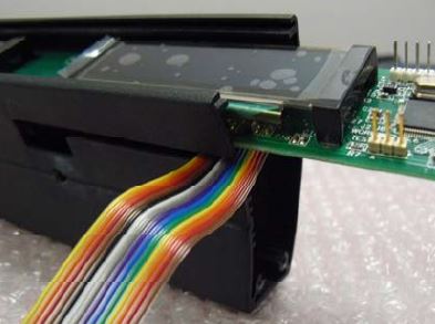
This will expose the inner pc board and plastic lens. You can slide the PCB out of the extrusion letting the ribbon cable slip though the slot in the end of the metalwork. This gives you access to the OLEDs and they can now be replaced.
(The lens has been removed for clarity. You can leave the lens in place.)
Replacing OLEDs
This step presumes that the display PCB WILL NOT need to be replaced. If your console needs to have the OLEDs and the PCB replaced, move on to the next step.
Begin by removing the four screws on the opposite side of the display.
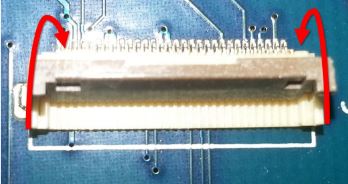
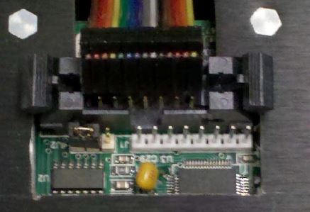
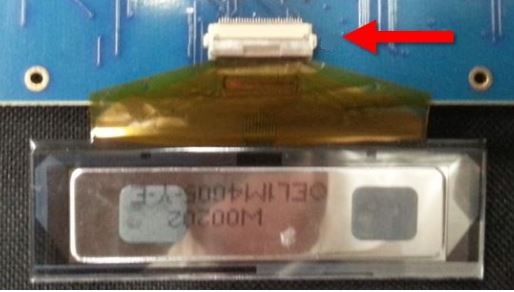
Once these screws are removed, the OLED will be free from the board. Do not lose the brackets or the screws. Carefully turn the board over and locate the ribbon connector which is behind where the OLED is normally mounted. Hinge open the connector from side facing the OLED, and the display will fall away from the PCB. Orient the new OLED in the way seen in the photo. With the contacts on the ribbon cable facing down, seat the connector in J1 and close it again.
Using the brackets and screws removed earlier, mount the new OLED to the PCB.
Installing Display Board
Install the new PCB in the same manner that the old one was removed and reassemble the meterbridge assembly by reversing the disassembly instructions.
Move back to the main console chassis and carefully insert the ribbon cable back the way it came out. Make sure the spacers go back into place between the overbridge and the console frame.
Because the chassis screws are removed from the frame, you can drop the chassis to expose the hole in the frame that will allow you to thread the ribbon cable back into place. When this is done, reattach the meterbridge assembly by reinstalling the two 5mm hex key screws. (the spacers are in place, right?) Then plug the ribbon cable back into the connector on the chassis.
Reinstall and tighten the 6 – 8 screws holding the console chassis to the frame. You’re almost done.
Replace the canbus hood and reinstall the 8 screws holding it in place.