Axia CANbus Specifications
 Updated
by
Bryan Jones
Updated
by
Bryan Jones
SCOPE
This document describes the electrical pin outs of the CAN bus cable used in Axia PowerStation, Element, Fusion, and QOR lines of consoles.
CONNECTOR
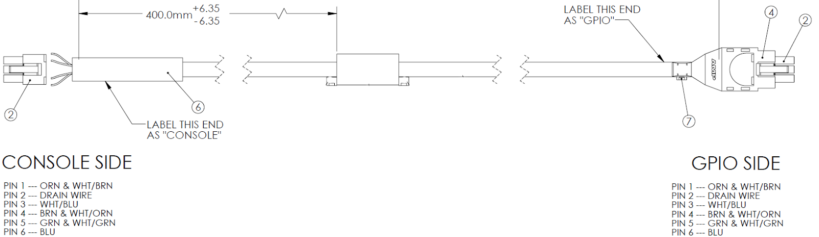
The standard CAN Bus supplied with your device has the same connector on both ends. Although it looks different the larger end simply has a shield around it.

- Pin 1 - 48v Gnd
- Pin 2 - GND Chassis
- Pin 3 - CAN (-)
- Pin 4 - 48v
- Pin 5 - CAN GND
- Pin 6 - CAN (+)
DRAWING OF THE CABLE
See our document on the cable components for more information.
PART NUMBERS OF AVAILABLE CABLES
CANbus cables (Fusion, Element & QOR) | ||
1711-00128 | GPIO-TO-ELEMENT POWER CABLE 20FT | default included with shipped product |
1711-00137 | GPIO-TO-ELEMENT POWER CABLE 10FT | |
1711-00150 | GPIO-TO-ELEMENT POWER CABLE 40FT | |
1711-00152 | GPIO-TO-ELEMENT POWER CABLE 25FT | |
1711-00153 | GPIO-TO-ELEMENT POWER CABLE 35FT | |
1711-00197 | PS to Element Splt Console | also 2091-00122-000 is same cable |
1711-00252 | GPIO-to-DESQ cbl 20’ | |
1771-00041 | Canbus Terminator Plug |
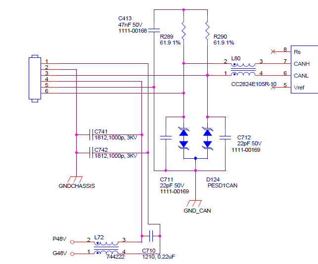
SCHEMATIC OF A STANDARD CAN BUS CIRCUIT
RJ45 PINOUT USED FOR INTERNAL CONNECTIONS
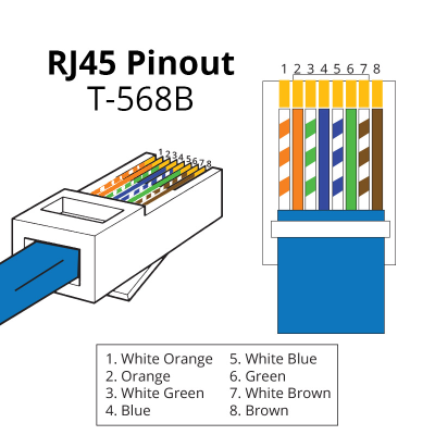
PINS USED FOR POWER
PIN # | Description |
1 | 48 Volt |
2 | Ref (GND) |
7 | Ref (GND) |
8 | 48 Volt |
PINS USED FOR DATA
PIN # | Description |
3 | Sig_GND |
4 | CAN_H |
5 | CAN_L |
6 | Sig_GND |