Cleaning and Lubricating Element (and Fusion) Faders
Scope
This article applies to Element and Fusion consoles with non-motorized and motorized faders.
Description
Over time, the operation of the faders on any console can become sluggish. Usually this can be remedied by cleaning and lubricating the fader's trolley and rail system. This article will show you how to disassemble the module and clean these components.
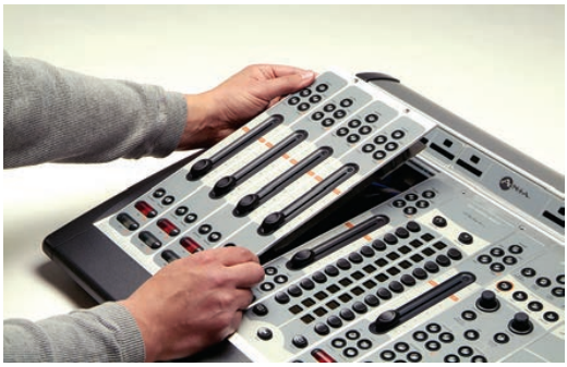
Remove the Input Module
- Use a 2.5 mm hex wrench to remove the retaining screws at the top of the module requiring service.
- With the screws removed, lift the module at the top, tilting it upward, and pull the locating tab at the bottom of the module from the mounting channel.
- Turn the module over and locate the ribbon cable that connects the module to its overbridge display . Gently press the “ears” on each side of the board connector to release the cable.
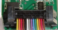
Make note of the orientation of the display cable. It's not keyed so you can plug it back in upside down. No damage will occur if you plug it back in incorrectly, it just won't work.
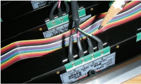
- Locate and disconnect the RJ-45 patch cable that connects the module to Element’s CANBUS distribution board.
The module can now be taken to the workbench for service.
Removing and Cleaning the Fader
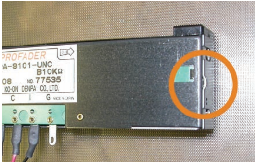
- Locate the four-conductor fader cable from the pins on the bottom of the fader. Follow the cable to the connectors on the module's circuit board and disconnect it.
There will be a second cable assembly to disconnect if faders are motorized.
- Now that the fader is disconnected, turn the module right-side up. Remove the knob from the fader to be serviced by pulling gently upward.
- Using a 1 /16” hex key, remove the two hex screws at the top and bottom of the fader slot. The fader will drop out from the bottom of the module.
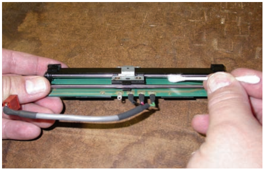
- Lay the fader assembly on your work surface, label-side up.
- Remove the snap-on fader assembly cover; it’s held in place by round stamped bosses at each end. With the fader sitting label up and the connector pins to the front, you’ll see a pry-point on the right end of the fader cover (shown below). Use a jeweler’s screwdriver to gently pry off the cover.
- Use compressed air, a dry cotton swab, or a cotton swab wet with distilled water to clean the fader parts.
- Use a clean dry swab to dry off the conductive plastic tracks (circuit board) after cleaning.
WARNINGS: If you need to slide the trolley out of the way, handle it only by the lever (T-shaped handle that holds the knob). The use of chemical cleaners on the conductive plastic tracks (circuit board) will substantially shorten fader life. Do not touch the conductive plastic tracks with fingers and take extra care to never touch the brush contacts on the underside of the trolley with anything. Deforming the brush contacts will ruin the fader forever.
Clean and Lubricate the Fader Trolley and Rails
Liquid to be used:
Ethanol: Absolute ethanol for cleaning
Lubricant: PAO or Fluorine Oil
Never use machining oil or cutting fluid.
- Touching the lever only (T-shaped handle that holds the fader knob), move the trolley to the middle of its travel.
- Using a cotton swab or precision oiler, place one small drop of lubricant on the top rail on either side of the trolley bushings.
ATTENTION: Do not allow the lubricants to come in contact with the conductive plastic tracks or the brush contacts on the underside of the trolley.
- Touching the lever only, move the trolley back and forth through its full travel to distribute the lubricant.
- Wipe off any excess lubricant from the rubber stops at each end of the glide rail.
Normally only the top rail that the the trolley bushings glide on (opposite the terminal strip) requires lubricant.
Reinstall the Fader
- Snap the cover back onto the fader body.
- From below, reinsert the fader into the input module, taking care that the end marked "∞" is in stalled adjacent to the channel’s On / Off keys.
- Reinstall the hex screws from the top of the surface. Do not over-tighten.
- Press the fader knob firmly onto the lever.
- Reconnect the cables to their corresponding connectors on the module.
Reinstall the Input Module
- Reconnect the Overbridge display ribbon cable, noting how it was connected before.
- Reconnect the RJ-45 CANBUS cable.
- Lay the module into the frame, engaging the locating tab at the bottom of the module and tilting the top downward into the frame.
Be careful not to pinch the ribbon cable between the module and frame.
- Reinstall hex-head screws at top of module.
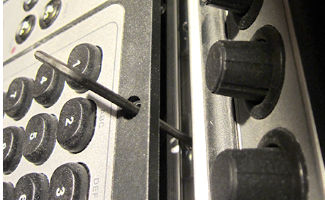
TIP: If needed, you can use your hex key to realign the sliding nut that accepts the hex screw:
Let us know how we can help
If you have further questions on this topic or have ideas about how we can improve this document, please contact us.