Pair the internal switch and I/O boards in a Power Station
 Updated
by
Bryan Jones
Updated
by
Bryan Jones
SCOPE
Applies only to Axia PowerStation MAIN (2001-00251)
DESCRIPTION
The internal PowerStation SOM board stores the mac addresses of the other devices under its control. In this case, they are the Switchboard and I/O board, which are both internal to the PowerStation. It’s important that these pairings are correct as it controls how the IP addresses are set for these devices. The IP addresses determine how they display on the Main PowerStation control panel web page
Assumptions
It is assumed that you have already assigned an IP Address to the PowerStation using the Monitor Nav module and that you have a PC connected and can navigate to the PowerStation Control Center web pages. Please see the documentation for your PowerStation and console if needed.
Start the “discovery” process
Point your browser to the main PowerStation Control Center webpage. Under the Mix Engine link on the left, click on Diagnostics as shown. At the bottom of that page, under the Hardware Configuration heading, click on the Discover… button
The next screen you see (it will take a while to load) will show you what the CURRENT mac address is that is paired (highlighted in GREEN) and what was currently FOUND in the system (shown in YELLOW). If you are installing any NEW hardware, it is possible that these two numbers will not match. Ideally what we want to see is that Switch boards found and Main IO boards found will always say “1”.
If they show more than one, please STOP HERE! and make sure you have read the warning above about not having your PowerStation connected to the rest of the network. If you do have an AUX PowerStation connected then it should also show AUX IO boards found: 1. Otherwise, it will show none as it is shown in the picture.
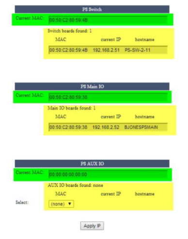
Once you have confirmed that only one board is found for each device type (PS Switch, PS Main IO) now you may click the Apply IP button at the bottom of the page. You will get a message that says “Discovering PS Boards, please wait”. This process will take some time, maybe a minute or two, so please be patient, the screen will return on its own when it’s complete.
This will internally write the “Found” information to the internal configuration files of your PowerStation and then it will attempt to set the IP Address of each of those devices in accordance to the IP Address scheme. The IP address of the PS Switchboard should always be +1 from the Main PowerStation IP address, The PS Main IO will always be +2 from the Main PowerStation IP and the PS AUX IO will always be +3 from the Main PowerStation IP Address.In the example shown above the PowerStation Control Center is at 192.168.2.50. As you can see the PS Switch is at automatically set to .51, the PS Main IO is set to .52 and if there were an AUX unit, it would be assigned .53
Verification
After this is complete, you should reboot your PowerStation and verify that all IP addresses are correct and that you can log in to the Subsystem Main, Subsystem Aux and the Switch sections of the PowerStation web interface
Let us know how we can help
If you have further questions on this topic or have ideas about how we can improve this document, please contact us.