Have one PDM control other PDM's at the same time
 Updated
by
Bryan Jones
Updated
by
Bryan Jones
Scope
This document applies to all 25-Seven PDM units. This includes;
- Generation 1 PDM units - Module B599 and LOWER.
- Generation 2 PDM units - Module B600 and HIGHER.
- PDM II units - new Generation PDM - has PDM II printed on the front of the unit.
- PDMx - Virtualized PDM units that run in a Docker container.
Description
This often used where a station might have some programming that is syndicated, or any any situation where two or more PDM units are used and you want to mimic the controls from a "leader" PDM to the "folower" PDMs
Step by step
Part 1: Configure Livewire GPIO on the Leader PDM
This is the PDM that you want to control your other PDM's from
- Log into the web gui
- Go to the Configuration tab
- Under "Livewire GPIO" Ensure that Livewire GPIO is enabled

- Find an unused GPIO port. Note the Port # you are using. In this example I am using Port 2
- Set the Outputs as follows: Pin 1 = BuildTrig, Pin 2 = Exiting, Pin 3 = DumpTrig
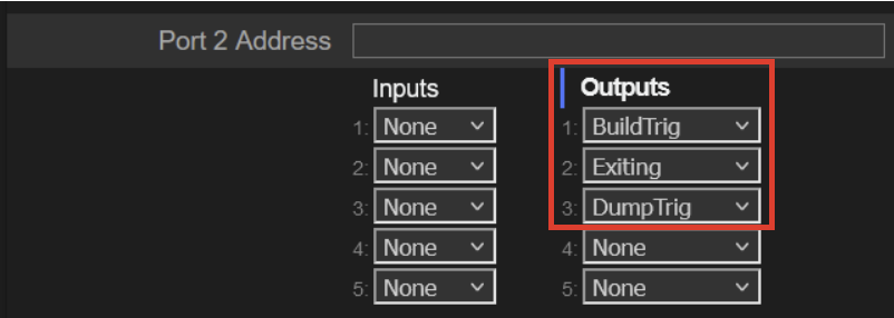
- Click the Apply button
Part 2: Configure Livewire GPIO on the Follower PDM(s)
- Log into the web gui
- Go the Configuration tab
- Under "Livewire GPIO" Ensure that Livewire GPIO is enabled
- Find an unused GPIO port.
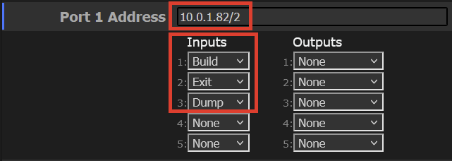
- Set the Inputs as follows: Pin 1 = Build, Pin 2 = Exit, Pin 3 = Dump
- Set the Port Address in this syntax:
IP_OF_THE_LEADER_PDM/GPIO_PORT_OF_LEADER_PDM
In this example: My leader PDM has an IP address of 10.0.1.82. From Part 1, Step 3, we are using GPIO Port # 2 on the leader PDM Which means that I want to set the Port Address of my Follower PDM to be:10.0.1.82/2
The follower PDM will connect to the leader PDM, on the desired GPIO Port. This is how the Follower will receive the commands from the Leader PDM
- Click the Apply button
Repeat Part 2 the same way for any additional PDM's that need to Follower the Leader PDM. You can have many PDM followers connected to the PDM leader for synchronous control of the three functions
Try it out
With both Leader and Follower PDM's, NOT in bypass, and with an empty delay buffer. Press the Build button on the leader PDM. The Follower PDM should also start to build. Same goes for Exit and Dump.
Please note. This is one way control. If someone pressed Dump on the follower PDM, the Leader PDM will not react. Only the Leader PDM will control the Followers.
Let us know how we can help
If you have further questions on this topic or have ideas about improving this document, please contact us.