iPort Status explained for GPIO and SNMP Traps
 Updated
by
Bryan Jones
Updated
by
Bryan Jones
SCOPE
This article applies to the Telos Zephyr iPort (all variants) and covers the version current as of this writing, presently 2.2.2a.
DESCRIPTION
The Telos Zephyr iPort offers both GPIO and SNMP notifications of errors. This document will describe each one and what the trigger is for the condition.
STATUS CONDITIONS
For purposes of this discussion when we refer to a pin being LOW, this is the "active" state. Think of it as a relay which is usually open but is now closed. Described another way, think of this as if this were a button you are actively holding.
Encoder Status ON
The assigned GPI pin is LOW when the Encoder is enabled. The status of the far end receiver is not considered here. Quite simply, is the Encoder enabled or not.
Encoder LW receive OK
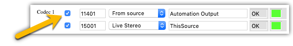
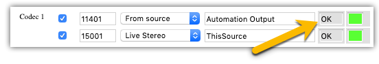
The assigned GPI pin is LOW when the Livewire channel assigned to the encoder is sending packets, and there are no errors in the data. The status window next to the Livewire channel will say OK. This would indicate no packet loss, no underruns or overruns, and no stream resumed errors.
Encoder LW audio present
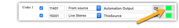
The assigned GPI pin is LOW when audio is present in the Livewire stream. If the signal level over 2 seconds is less than -52 dBfs, it is assumed that there is no audio signal. Anything over that level indicates audio and is also shown as the green dot on the web page.
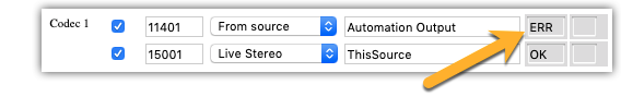
Encoder LW receive lost
Opposite of Encoder LW receive OK.
The assigned GPI pin is LOW when there are no incoming LW packets over a specific time period. For those interested in the technical details that is half of the Standard Audio Streams buffer size in ms. Receive loss shows as an ERR in the status window.
Encoder LW buffer error
The assigned GPI pin is LOW when there are LW overruns/underruns, LW stream resumed, LW RTP packet timestamp defects. There is no level or threshold for this alarm. Every instance triggers an alarm.
Encoder Alarm
This is a "General Alarm" and is triggered if the encoder encode function returns an error For example, if it can't send encoded frames to the destination, or if some other encoder-specific issues occur. Active only if encoder is enabled.
Decoder status ON
The assigned GPI pin is LOW when the Decoder is enabled. The actual reception of data from the far end is not considered. Simply, is the Decoder enabled or not.
Decoder WAN receive OK
The assigned GPI pin is LOW when and OK is shown in the Decoder receive status. OK indicates that packets are not only received but have also been properly decoded. There must be an incoming stream for more than 1 second with no packet loss and no dropped packets in the receiver due to a buffer overflow.
Decoder LW audio present
Similar to the Encoder audio status, the assigned GPI pin is LOW when audio is present on the decoded stream and is present in the outgoing Livewire channel. If the signal level over 2 seconds is less than -52 dBfs, it is assumed that there is no audio signal. Anything over that level indicates audio and is also shown as the green dot on the web page.
Decoder WAN receive lost
Opposite of Decoder WAN receive OK.
The assigned GPI pin is LOW when the Decoder is receiving no data for more than 1 second. In this case, there is NOT an OK indication in the Decoder.
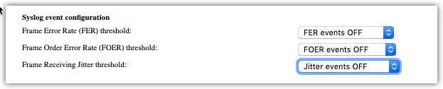
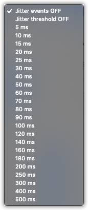
Decoder WAN jitter alarm
This is triggered by the configuration option "Frame Receiving Jitter threshold". If the measured jitter value exceeds the user-configured value, the alarm is set to ON. Choices for WAN Jitter are shown here.
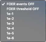
Decoder WAN sequence alarm
This is triggered by the configuration option "Frame Order Error Rate (FOER) threshold". If the measured FOER value exceeds the user-configured value, the alarm is set to ON. Choices for FOER thresholds are shown here. Setting the threshold OFF will report every order error.
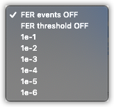
Decoder WAN FER alarm
This is triggered by the configuration option "Frame Error Rate (FER) threshold". If the measured FER value exceed the user-configured value, the alarm is set to ON.
FER is calculated as function from total received packets, lost packets and packet sequence errors over a specific time interval. The choice shown here are 1e-1 (1 error in 1 sec), 1e-2 (1 error in 2 seconds), etc. If you turn the threshold OFF, it reports every frame error.
Decoder alarm
This is a "General Alarm" and can be triggered by a specific Decoder function returning an error, or a non a specific error. For example, an active decoder count limit has been exceeded.
Decoder receive path A alarm
The assigned GPI pin is LOW when there is packet loss in Path A
Decoder receive path B alarm
The assigned GPI pin is LOW when there is packet loss in Path B. This is active ONLY if redundant WAN path functionality is enabled.