Configuring Netgear M4250 switch for Livewire+ AES67
 Updated
by
Brett Patram
Updated
by
Brett Patram
Scope
The Netgear M4250 AVLine series of managed switches can be a good solution when building out a new small to medium-sized AOIP network. This HelpDoc will serve as a basic configuration guide to configure the M4250 to support an AOIP network. These days it is not uncommon for an AOIP network to consist of several different standards of AOIP streaming. The M4250 series provides a simplified way to configure the switch with optimal settings to support a mixed Livewire+ and AES67 AOIP network
Disclaimer - Read This First
This configuration guide is provided without warranty. Telos Alliance is not responsible for any issues that may be encountered. Telos Support is not the responsible party to provide additional support in configuration or troubleshooting.
Contact Netgear Support for questions regarding network topology, switch models, configuration, troubleshooting or software updates. Netgear provides excellent support to its customers. Please also see their Knowledge Base for the M4250 series
If you have an existing AOIP network built on a different brand of switches do not attempt to add the Netgear M4250 into the environment.
At this time we do not suggest interfacing the built-in switch found in Axia QOR, xSwitch or Powerstation with the Netgear M4250.
Programming
Connecting to the switch for the first time
All switch configurations can be done from the web browser.
The switch's web ui can be accessed from the dedicated Out Of Band management port "OOB" or from any of the regular Ethernet switch ports
Please reference the Installation Guide and review the section "Access the AV UI or main UI to configure the switch" for instructions for connecting to the switch via the OOB port or the regular Ethernet port
Login
The switch has two different user interfaces you can log into to perform configuration tasks
Please use the AV UI Login.
First time login: Login Name is admin, Leave the password field blank. You will be prompted to set a password after login
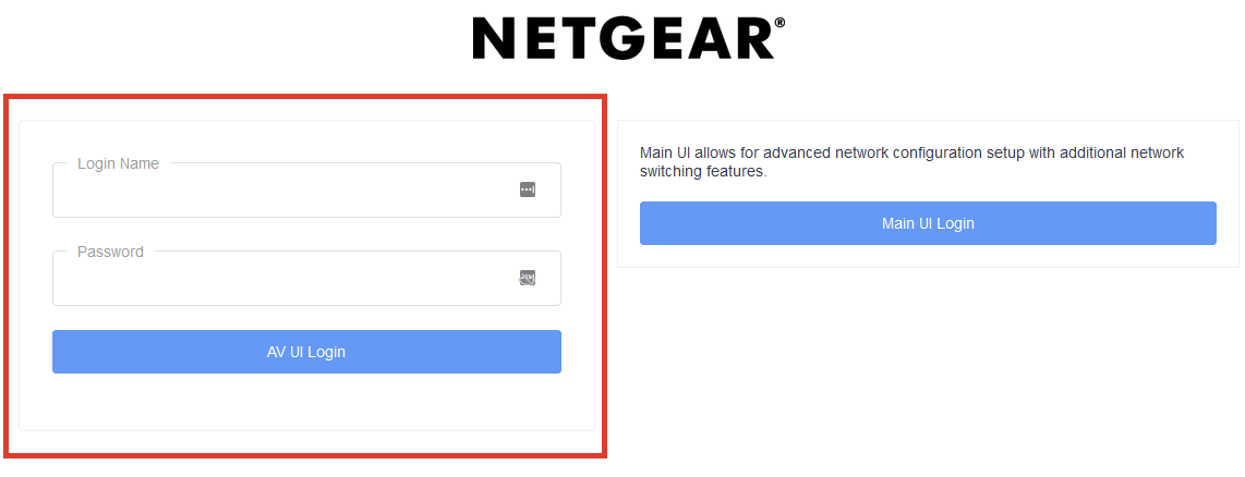
If you do not see a similar login page as shown above, please update switch firmware
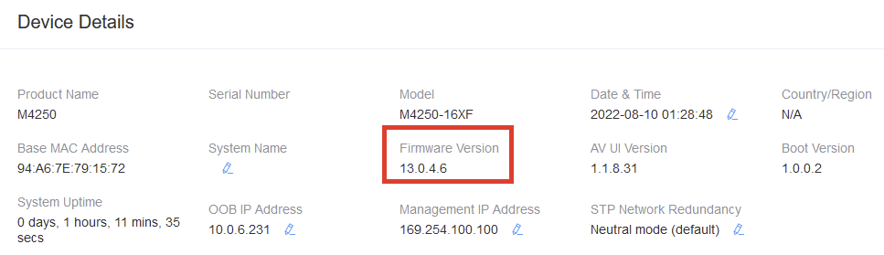
Check/ update firmware
Before proceeding, check the Firmware Version shown on the Device Details section of the Overview page.
Check the Netgear Download Center for the latest switch Firmware and update if necessary
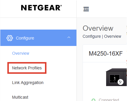
Assign Network Profiles to Ports
- On the left hand navigation menu select "Network Profiles"
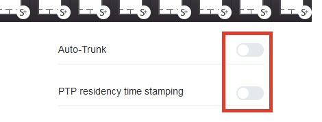
- At the top of the page, we recommend turning off Auto-Trunk, and turning off PTP residency time stamping
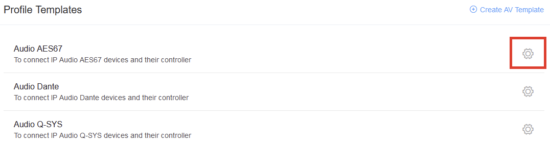
- Under the Profile Template section of the page, click the Gear icon next to Audio AES67
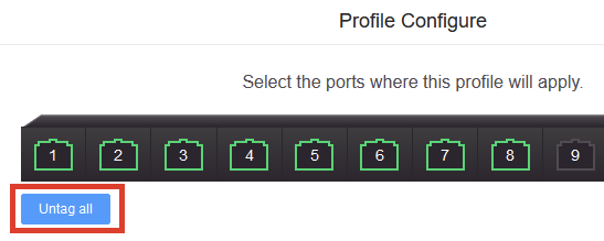
- On the Profile Configure pop-up, click the "Untag All" button. Green check boxes should appear on all ports
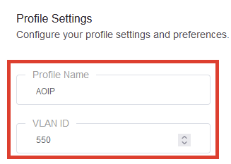
- On the Profile Configure pop-up, provide a unique "Profile Name" and select a VLAN ID
The VLAN ID used can be user defined. However, do not use VLAN ID 1. Click the Apply Button when complete
Configure Device Details
Go back to the Overview page and back to the Device Details area
The pencil icon allows you to adjust each parameter
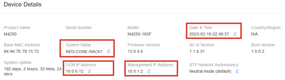
- Set "System Name" to set the hostname of the switch
- Set the Date & Time
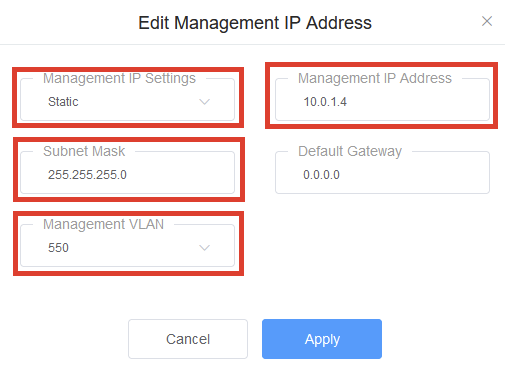
- Set the Management IP Address
Note, this will provide access to the switch web gui from the Ethernet ports.
If this switch is operating standalone, or it is the main switch other switches will connect to set "The Management IP Address " to be the lowest IP address of the other edge switches that may also be connected later. This address influences the IGMP Querier election process
The Management IP Address and Subnet should match that of your AOIP network range
The Management VLAN should match that of the VLAN ID that was used in the Network Profile configuration
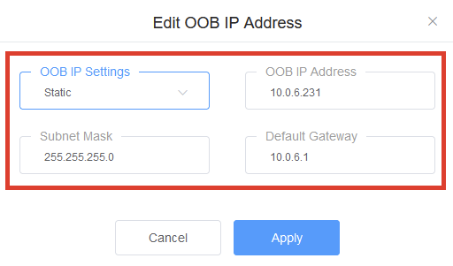
- OPTIONAL: Set the OOB IP Address
If you wish to set a Static IP Address on the OOB port change OOB IP Settings to "Static", and complete the other fields
The OOB port only allows access to the web GUI. You can assign this port and address that fits within an existing network subnet for other device management-only interfaces. Sometimes referred to as a Management LAN. If you do not need this, please skip this step.
Save changes to the switch
IMPORTANT! Please click the Save button at the top of the page to save the configuration to memory. Otherwise all changes will be lost if the switch is rebooted or powered down

That's it! If you have additional edge switches please repeat the steps above, but increment the Managment IP address by at least one octet higher than this switch.
Confirming IGMP multicast operation
Start connecting the various AOIP devices to the network (xNodes, Engines, Intercom panels, etc)
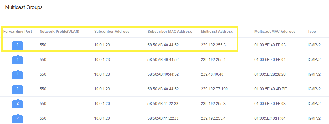
Check that multicast groups table starts populating
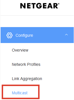
On the left hand navigation select Multicast
The multicast group's table should start showing entries as more devices come online and start requesting Livewire or AES67 multicast streams.
Confirm that IGMP Querier Election is correct
If there are multiple Netgear switches installed we can confirm that the IGMP Querier is only running on one switch (core switch). We can confirm that the edge switches indicate IGMP Querier is coming from the core switch
On the left hand navigation click on Diagnstoics and then select Terminal
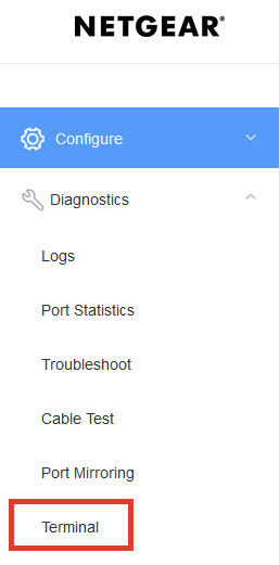
You will be prompted to log in from the CLI, use the same credentials used for the web ui
On the core switch, or central switch type in the command "show igmpsnooping querier detail"
For the VLAN defined in previous steps, VLAN 500 in this example we observe the "Operational State" shows "Querier"
(RED-CORE-RACK1)#show igmpsnooping querier detail

VLAN 550 :   IGMP Snooping querier status
----------------------------------------------
IGMP Snooping Querier VLAN Mode................ Enable
Querier Election Participate Mode.............. Enable
Querier VLAN Address........................... 0.0.0.0
Operational State.............................. Querier
Querier MAC Address............................ 94:a6:7e:79:15:72
Operational version............................ 2
Operational Max Resp Time...................... 120

(RED-CORE-RACK1)#
Repeat the same command but do this on any connected Edge switches
For the same VLAN, we observe the "Operational State" shows "Non-Querier"
Additionally "Last Querier Address" should equal the Management IP of the switch that is running the IGMP Querier
(RED-EDGE2-RACK1)#show igmpsnooping querier detail

VLAN 550 :   IGMP Snooping querier status
----------------------------------------------
IGMP Snooping Querier VLAN Mode................ Enable
Querier Election Participate Mode.............. Enable
Querier VLAN Address........................... 0.0.0.0
Operational State.............................. Non-Querier
Last Querier Address........................... 10.0.2.5
Querier MAC Address............................ 94:a6:7e:79:15:72
Operational version............................ 2
Operational Max Resp Time...................... 120

(RED-EDGE2-RACK1)#