How to use a User Module in Fusion or Element consoles
 Updated
by
Bryan Jones
Updated
by
Bryan Jones
Scope
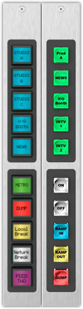
This document covers the different operating modes of User Modules mounted in a Fusion or Element console. There are two basic modules shown here. There is an LCD version that can display text and a Film Cap version, which would require the use of a label under the switch cap.
This document only covers Fusion or Element. These modules are not compatible with Quasar, iQ, Radius, or iQx.
Description
Customers will often ask, "what are the control options for user modules in my Fusion (or Element) console?". There are three operating modes.
- User Module
- GPIO Module
- GPIO Snake
We will cover the differences in these modes here, however, will not focus on a specific setup.
Properly installed modules will be automatically detected by your console and listed under User Modules on the configuration web page.
Operation Roles
To chose the role of your User Module;
- Navigate to the setup web page of your Fusion or Element console.
- From the left-side menu, click on the User Modules link.
- For each user module, select the desired operating role.
- Click Submit.
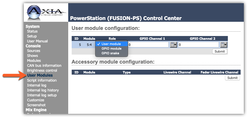
User Module role
In this mode, the user modules are mostly "dumb" and have no pre-assigned functions. It's up to you to program each button. Most of the time the programming of the buttons is achieved by using Axia Pathfinder Software (sold separately). Many Radio Automation systems can control or be controlled by buttons set as User Module.
In this mode, the user can control;
- Button State (ON or OFF)
- Button Color when ON
- Button Color when OFF
- Button Text (LCD Module only)
The defaults for all both modules are;
- White - ON State
- Black - OFF State
- Text - None (LCD Only)
GPIO Module role
In this mode, each set of 5 buttons is assigned a Livewire channel. The functions of the buttons are determined by the "type" of the source that is assigned. GPIO for each type is detailed logic tables in the manual.
As an example, if you were to assign Livewire Channel 12345 and, this Livewire channel was defined as a "Line Input" source type, the buttons would be, ON, OFF, PREVIEW, RESET, READY. They would perform that function when pressed, and the lamps would respond accordingly. In other words, Button 1 would turn ON when the console was on. Button 2 would turn on when the console was off, etc.
In this mode, the button functions and states are pre-defined. You can not set the colors or text of the buttons in this mode.
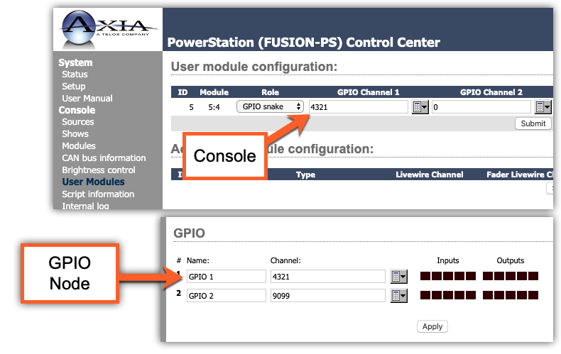
GPIO Snake role
In this mode, the GPIO Channel is used to communicate with another GPIO node. For example, assign channel 4321 in the User Modules page and also assign 4321 to a port on a GPIO Module as shown here;
When user Button 1 is pressed, GPIO output Pin 1 will go Low. Press Button 2, GPIO output Pin 2 goes low. This behavior is the same for all five buttons.
Using external control, if you close Input 1 on the GPIO node, Button 1 will turn on. Input 2 on the GPIO node turns on Button 2, etc.
In this mode, the button states are controlled by EXTERNAL GPIO. You can not set the colors or the text of the buttons in this mode.
Let us know how we can help
If you have further questions on this topic or have ideas about how we can improve this document, please contact us.