Quasar MF1-ACC and MPC-ACC Modules
 Updated
by
Bryan Jones
Updated
by
Bryan Jones
Scope
This document applies to the Quasar Microphone and Headphone controllers (both with and without the fader).
- 2001-00575-000 - MPC-ACC Module, Mic/Headphone Control Module
- 2001-00576-000 - MF1-ACC Module, Mic/Headphone Control Module with Motorized Fader
Description
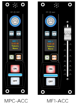
The MF1-ACC module (with Motor Fader) and the MPC-ACC module (without fader) are optional Accessory Modules designed to provide the Talent with direct control of his Microphone and Headphone monitor, right in the studio.
Every Quasar Accessory Module has 2 Gigabit PoE ports, with a network switch built-in, to allow for daisy-chaining Ethernet without the need for an external switch.
The Accessory Modules require a standard PoE connection to operate. Connecting these modules to a PoE+ switch will not work unless the switch has the ability to automatically switch its ports to standard PoE.
Wiring
Several connection schemes are supported
- Connect directly to a switch that provides PoE power with a minimum 802.3af specification.
- Connect directly to any other switch in the network via the use of an 802.3af capable PoE Injector.
- Connect directly to the second Ethernet port of the Quasar console frame with the addition of an external PoE injector.
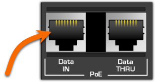
- Connect the main Ethernet cable (with PoE power) to the Data IN port on the first accessory module.
- Connect the next accessory module in the chain from the Data IN of the second module to the Data THRU of the first module.
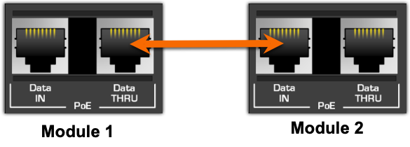
- Repeat step 2 for (possibly) a third module. (See PoE Considerations below)
POE Considerations
The 802.3af PoE standard allows for a max PoE budget of 15.4 watts per port.
The MPC-ACC (the one without the fader) draws between 5.0 watts and 6.4 watts depending on the brightness setting. A brightness of 100% should never be required and is hard on the equipment. However, if you are in a very bright environment and require this setting, only two modules should be connected so that max PoE power is not exceeded.
The MF1-AAC (the one WITH the fader) draws between 5.0 watts and 8.4 watts depending on brightness setting and fader movement. ONLY TWO MF1-AAC MODULES SHOULD BE DAISY-CHAINED.
Additional Warnings
Most PoE injectors are not "smart" and may damage an accessory module or the PoE injector if max power is exceeded or if it's plugged into the Data THRU port of your accessory modules.
Adding modules to Quasar
Accessory modules are added to Quasar by using the XR/ACC Module link under the Configuration options from the main Quasar Web Page.
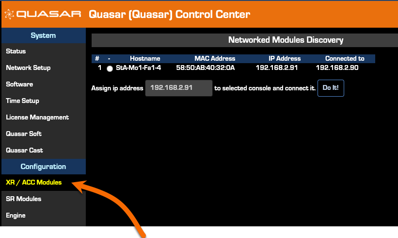
Once connected, these modules will be discovered on this page where you can assign an IP address (each module requires a unique IP address).
Module Configuration
Module configuration is completed by accessing it directly using your web browser, similar to configuring other Quasar components. There are many options for configuration. Only the basics are listed here.
- Using a Web Browser, enter the IP Address of the first module you want to configure.
- Log in with the name "user" and leave the password field blank.
- Navigate to the Network Setup page on the left side menu.
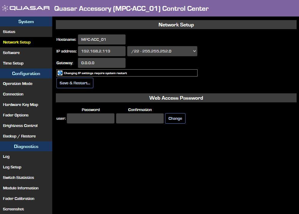
Here, you can set the Hostname to something more descriptive. For example, change to ST1-G1-ACC. This name might represent Studio 1 - Guest Position 1 - Accessory module. Changing the name to something meaningful will help you identify individual modules later.
From this page, you can also change the web access password.
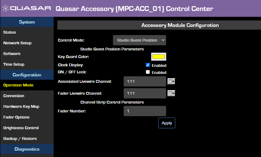
- If you will be displaying Time of Day (Clock Display option under Operation Mode) make sure to navigate to the Time Setup page and set your time sync option.
- The primary configuration begins on the Operation Mode page found under the Configuration heading.
Module Dimensions
For illustrations on precise measurements of these modules, click here.
Let us know how we can help
If you have further questions on this topic or have ideas about improving this document, please contact us.