Configuring MPX Nodes for redundant streams
 Updated
by
Jake Alderman
Updated
by
Jake Alderman
SCOPE
Version 1.3.35 of the Omnia MPX Node adds redundant streaming capability. This document assumes the IP addresses have already been assigned to both network interfaces on each MPX Node. For assistance setting the IP address of the MPX Node please see the Quick Start Guide.
The design shown here is one method to build system redundant streams. Designs for more complex applications can be extrapolated from this document.
DESCRIPTION
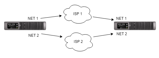
If multiple IP networks are available, it is possible to send redundant streams and have the decoder reconcile MPX signals on a packet-by-packet basis. For this example, there will be 2 internet service providers at both the Studio and Transmitter sites.
Requirements
- Version 1.3.35 or newer software is required. If the MPX Node needs to be updated please click here.
- You must know both of the public static IP addresses
- Port forward the same port through both firewalls at the transmitter site
Configuring the Decoder MPX Node
- Using your web browser, navigate to the main web page of your decoder MPX Node.
- Log in with your user name and password.
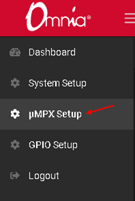
- Open the µMPX Setup Menu
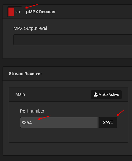
- Turn off the µMPX Decoder
- Find the stream receiver section
- Set the Main port number to the one that is forwarded through both routers
- Click Save
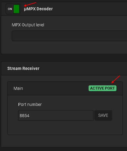
- Turn on the µMPX Decoder
- Make sure the main port shows as the active port
Configuration of the Decoder is now complete. Move on to configuration of the encoder MPX Node for system testing.
Configuring the Encoder MPX Node
- Using your web browser, navigate to the main web page of your encoder MPX Node.
- Log in with your user name and password.
- Open the µMPX Setup Menu
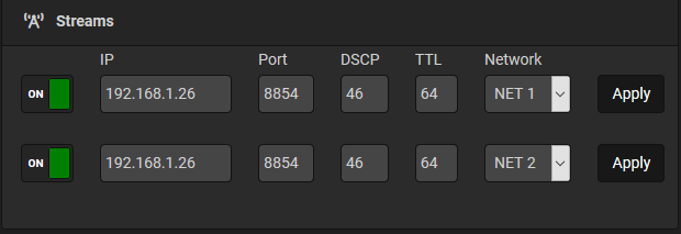
- Scroll down to the Streams section
- In the first stream type the Public IP Address that should act as the primary receiver
- Type in the port number that is forwarded through the firewall
- Using the Network drop-down select the NET 1 Interface
- Click save
- Turn the stream on
- In the second stream type the Public IP Address that should act as the primary receiver
- Type in the same port number used in Step 6 that is forwarded through the firewall
- Using the Network drop-down select the NET 2 Interface
- Click save
- Turn the stream on
When finished, both NET 1 and NET 2 will be sending to the same IP and port address, but over separate networks.
System Testing
In the following testing, you are basically toggling between encoder streams to prove that, so long as one stream is being sent, a signal continues to be received at the Decoder.
- Using your web browser, navigate to the main web page of your decoder MPX Node.
- Log in with your user name and password.
- Open another tab or browser window
- Navigate to the main web page of your encoder MPX Node.
- Log in with your user name and password.
- Open the µMPX Setup Menu
- Scroll down to the Streams section
- Verify both streams are in the on position
- Turn off the first stream
- Open the tab or window with the decoder
- Verify it still receives a stream
- Open the tab or window with the encoder
- Turn on the first stream
- Wait 5 seconds
- Turn off the second stream
- Open the tab or window with the decoder
- Verify the MPX Node still receives a stream
With testing complete, the system is now ready to go on air.