Configuring Cisco SG350 Series of Switches for Livewire+®
 Updated
by
Bryan Jones
Updated
by
Bryan Jones
Introduction
This document is not an all-inclusive or even a step-by-step manual on how to configure this switch fully. It is provided as a guide and makes some underlying assumptions regarding the person's skill level doing the programming. If you are not comfortable hooking up cables, assigning IP addresses, typing in a command-line interface, configuring networks, etc., you should contact your IT department for assistance.
Unlike its big brother in the Catalyst line of Cisco switches, some portions of this configuration caused audio to be briefly interrupted. For that reason, it is best to carefully plan for making any changes to this switch while it's in use. We observed interruptions of thirty seconds to a minute; however, the switch ALWAYS recovered.
We tested this switch for use with Axia Power Station, QOR console, iQx Console, and xSwitch with other Axia gear. All tests performed well, except for the noted outages.
Given the relative cost savings between the Catalyst and the SG line, each user will need to balance their own risk vs. reward.
Testing has shown the SG350 is appropriate in a single switch system or smaller systems of, say, three or four studios. In larger, multi-swtich systems, a Cisco Catalyst is a better choice.
Configuration
This switch tested, and the configuration is based on the following;
- Cisco model: SG350-28
- Firmware Version: 2.4.0.91
Programming
Using Configuration Wizards
Using the “Getting Started Wizard,” you will set the following information;
- System Location, Contact, and Host Name (if desired)
- IP Address settings
- User Account
- Time Settings (if desired)
As an example, a network with;
- Power Station at 192.168.2.50
- QOR Console at 192.168.2.27
- Axia xSwitch at 192.168.2.4
We would want this switch to be lower than the xSwitch with the .4 address programmed on it. For this example, we will program our switch to have an address of 192.168.2.2.
To get started:
- Click on the Configuration Wizards link in the left-side menu.
- Choose Launch Wizard under the Getting Started Wizard heading.
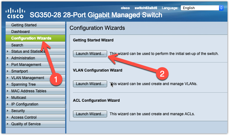
You will be presented with a new window to begin the configuration. Click Next to begin. You will be presented with the following screen. Fill out any desired information and click Next.
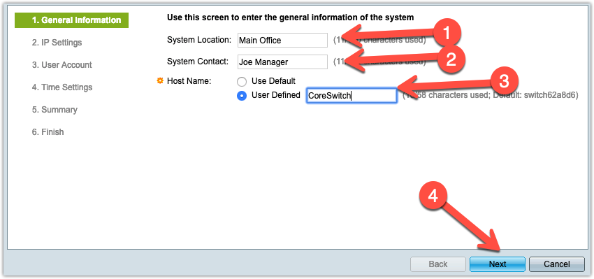
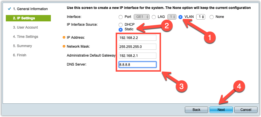
On the next page:
- Click the selector next to VLAN and pick ‘1’ from the dropdown list if not already selected.
- Select Static from the IP Interface Source.
- You must specify at least an IP address and Network mask. Default Gateway and DNS are optional and will vary depending on your situation.
- When finished, click Next.
The next TWO screens, User Account and Time Settings, are optional. You can use these to change the login information and time settings if NTP is used. NTP may require that you configure a gateway and DNS in the previous step
Finally, you will get to the Summary page, and click Apply.
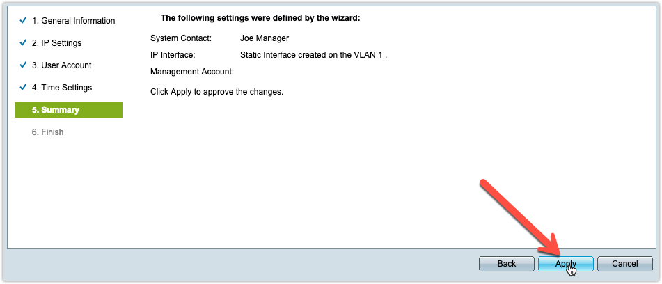
At this point, clicking Apply will change your IP address, and you will need to reconfigure your network settings on your computer and connect to the new IP address via your Browser.
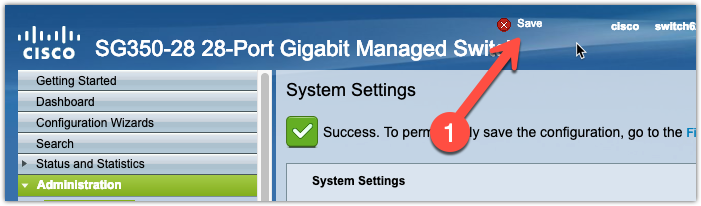
Once you are logged back into your configuration web page, this is an excellent time to save your configuration by clicking the save button, which you should see flashing at the top of the configuration web page.
Configure IGMP
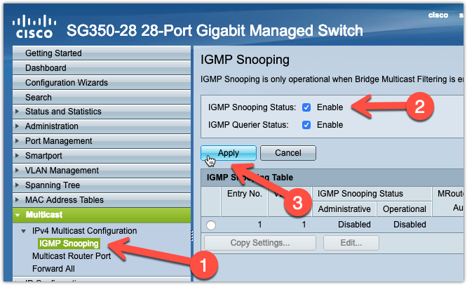
To configure IGMP, select Multicast from the left side menu. Expand IPv4 Multicast Configuration and choose IGMP Snooping. Adjust the settings as shown here and click Apply.
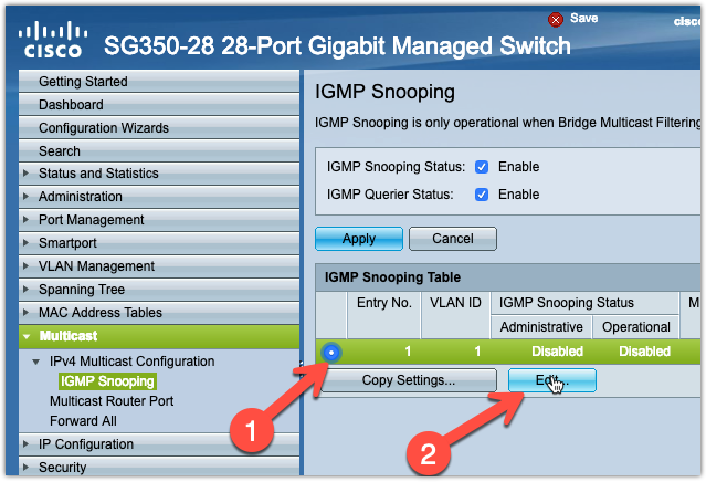
Next, select the bubble next to VLAN ID 1 (at this point, there should only be one) and then click Edit.
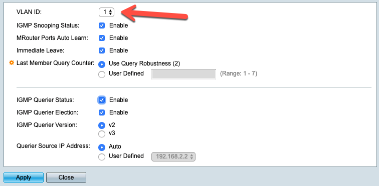
On the next window, make sure VLAN ID 1 is selected, adjust the settings as indicated in this next image, click Apply, and then click Close to dismiss the configuration window.
For the next step, we need to change the Display mode to Advanced. This is done in the top right corner of the browser window. From the dropdown list, pick Advanced. This mode will give you additional options in the left menu. Under the Multicast menu heading, select Properties. Set the options on that page, as shown here. Make sure that VLAN ID 1 is selected. Click Apply when finished.
Using the Display Mode, set your menu back to Basic.
Configuring QoS
From the left side menu, select Quality of Service, expand QOS Basic Mode, and select Global Settings. Select DSCP as the Trust Mode. Click Apply when finished.
Next, expand General and select DSCP to Queue. Set the options for each DSCP class, as shown here. Note that Axia Live Stereo and AES67 streams use DSCP 48, which we assign to the highest priority queue (8). Axia Standard Stereo streams use DSCP 46, which we assign to queue 7. For this configuration, other DSCP classes are assigned to lower-priority queues.
Configuring Access Ports
All ports on this switch are, by default, configured as Access ports. So, no changes should be required. Verify this by navigating to the VLAN Management link on the left side menu and selecting Interface Settings. Observe the current settings in the table that is displayed.
Configuring Trunk Ports
In this example, we are going to be configuring ports 22 to 28 for use as Trunk ports.
From the VLAN Management menu, make sure that Interface Settings is selected. Click the selection bubble next to the first port that you want to configure as Trunk. In this example, port 22. Click the Edit button.
In the window that opens, select Trunk, as shown, and click Apply when done.
You can continue like this and set each port to Trunk individually. However, you can apply this setting to the remaining ports automatically. Make sure that your newly configured Trunk port (port 22) is selected, and then click Copy Settings. In the window that opens, type the ports that you want this configuration copied to. In our example, we have typed 23-28, which will copy port 22 to ports 23 through 28. Once you have your port range defined, click Apply.
You will see that your settings have been copied to the additional ports.
Configure Power Management Settings
Select Port Management from the Left menu tree, Expand Green Ethernet, and select Properties. Set your Green Ethernet settings as shown here.
Saving and Backing Up your Configuration
To save your configuration, navigate to Administration on the left menu. Expand File Management and select File Operations. Choose the settings shown here and click Apply.
To back up your settings, choose File Operations again, change your settings as shown here, and click apply. This will copy your configuration to a text file on your computer.
Let us know how we can help
If you have further questions on this topic or have ideas about improving this document please contact us