Using a Paravel Systems WallTime On-Air light with Axia consoles
 Updated
by
Bryan Jones
Updated
by
Bryan Jones
Scope
This document applies to the configuration of the Paravel System WallTime and the use of the On-Air light feature. WallTime has many options for the configuration of the On-Air light, however, for this document, we will cover setup using the Control Room Monitor Logic port from an Axia console.
While the actual configuration of Quasar, Fusion, iQ, and iQx consoles slightly different, the logic from this port is exactly the same.
We will use an iQ console for this example.
Configuring your Console
- Using a Web browser, navigate to the configuration page of your iQ console.
- From the Menu on the left side, click on the Shows link and log in with your user name and password.
- From the four shows that are listed, click on the name of the one you want to configure.
- Scroll down to the Monitor Section and locate the Logic port setting under the CR Monitor column as indicated here in this picture.
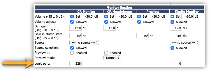
- Enter any unused available Livewire channel. Since audio and GPIO travel together, this should not be a channel that might get used elsewhere. In this example, we have chosen channel 228.
- Click OK at the bottom of the page.
Configuring WallTime
Like Axia devices, you configure WallTime using your Web browser. For full details on configuration, we refer you to the WallTime site.
The IP Address of your WallTime is shown in the bottom left corner of the screen below the Paravel Systems logo.

- Using your Web browser, log in to the configuration page for your WallTime. You will be required to supply a user name and password. By default, the user name is "user," and the password field is left blank.
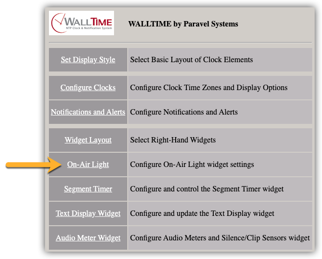
- Click on the On-Air Light link to configure the On-Air Light widget settings.
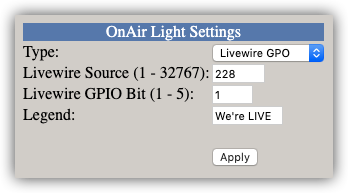
- For Type, select Livewire GPO.
2023-05-01
* Renamed the 'Livewire GPI' GPIO type to 'Livewire Node GPI' in
the web UI.
* Renamed the 'Livewire GPO' GPIO type to 'Livewire Surface button
GPI' in the web UI.
Please make the appropirate selction for the version of sofware you are running.
- For the Source, enter the channel number you specified in the previous steps. From our example, we used channel 228 for our Logic Port.
- For the GPIO Bit, enter 1.
- Enter something clever for the Legend (or not). This is what is displayed on the screen when active.
Here is an example of the properly configured On-Air Light settings.
Configuring your Widget Layout
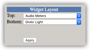
The On-Air light can be placed on either the Top or Bottom of the Widget layout.
- From the WallTime menu, select Widget Layout from the Home menu (alternately, Widgets if the menu is across the top of your screen).
- From the drop-down list, you must assign On-Air Light to one of the Widget locations. Here you can see we have assigned it to the Bottom location.
- Click Apply.
Testing your configuration
If you have configured your WallTime correctly you should now see your On-Air light as shown here.
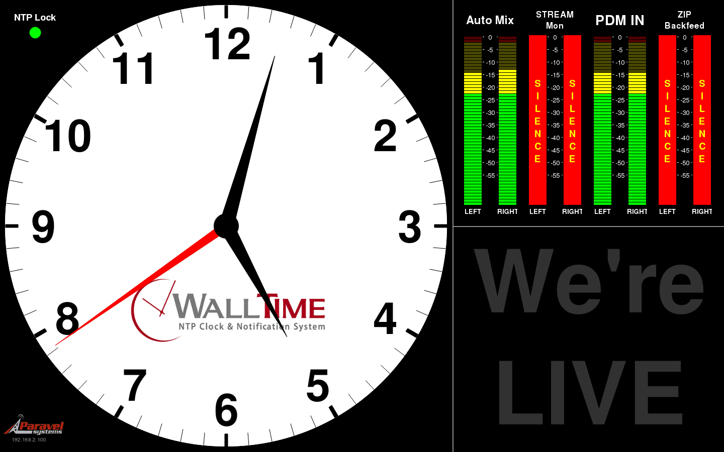
When you turn on your microphones on the iQ so the monitors mute, your WallTime On-Air Light will activate as shown here.

Congrats, you are all done!
Let us know how we can help
If you have further questions on this topic or have ideas about how we can improve this document, please contact us.