Confirming operation of a QOR via use of the internal serial port
 Updated
by
Bryan Jones
Updated
by
Bryan Jones
Scope
This document will instruct you on how to use the internal serial port on a QOR16 or QOR32 to confirm if the unit is booting. This procedure requires disassembly of the QOR as well as the need to build a special serial cable. This serial cable connects to a three-pin header inside the QOR.
This document covers the following Telos part numbers;
- 2001-00274 QOR.16 INTEGRATED CONSOLE ENGINE
- 2001-00276 QOR.32 INTEGRATED CONSOLE ENGINE
Tools
For this procedure you will need the following;
- #2 Phillips screwdriver
- 3 mm Allen wrench
- Special serial cable
Building the Cable
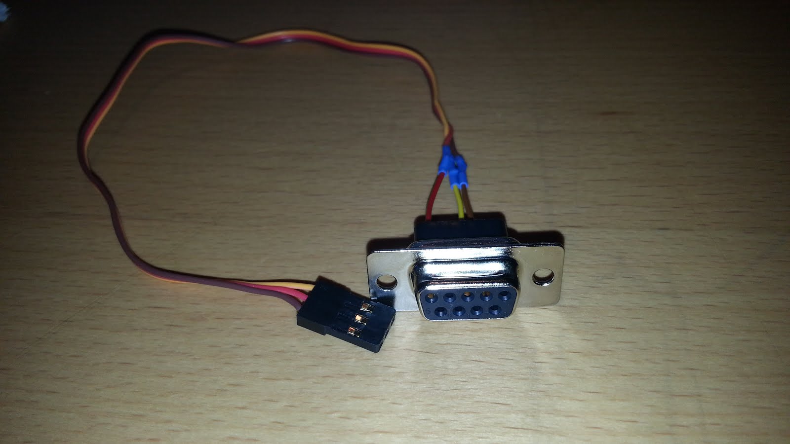
This picture shows the serial cable that is required. This a standard DE-9 Female connector on one end and a three-pin connector on the other that connects to the main board of the QOR. The connector on the mainboard is a standard 0.1 spacing connector.
A good source for this cable is a Futaba 12 inch servo extension cable. It is a good length, and one end can be removed and fitted to a proper DE-9 connector per the pinout guide. A Google search for “Futaba servo extension cable” should yield many results.
Pinout
The pinouts for this cable are as follows;
DE-9 | Board Header |
Pin 2 | Pin 1 |
Pin 3 | Pin 3 |
Pin 5 | Pin 2 |
The following procedures require you to remove covers and other parts that are placed there for safety. Disassembly and service should be performed with all power disconnected and only by qualified personnel.
***************************
Cable Usage
Remove the cover from the QOR by removing the Phillips head screws from the top of and two sides of the cover, as well as the top two 3 mm Allen head screws from the front of the QOR.
Header Identification
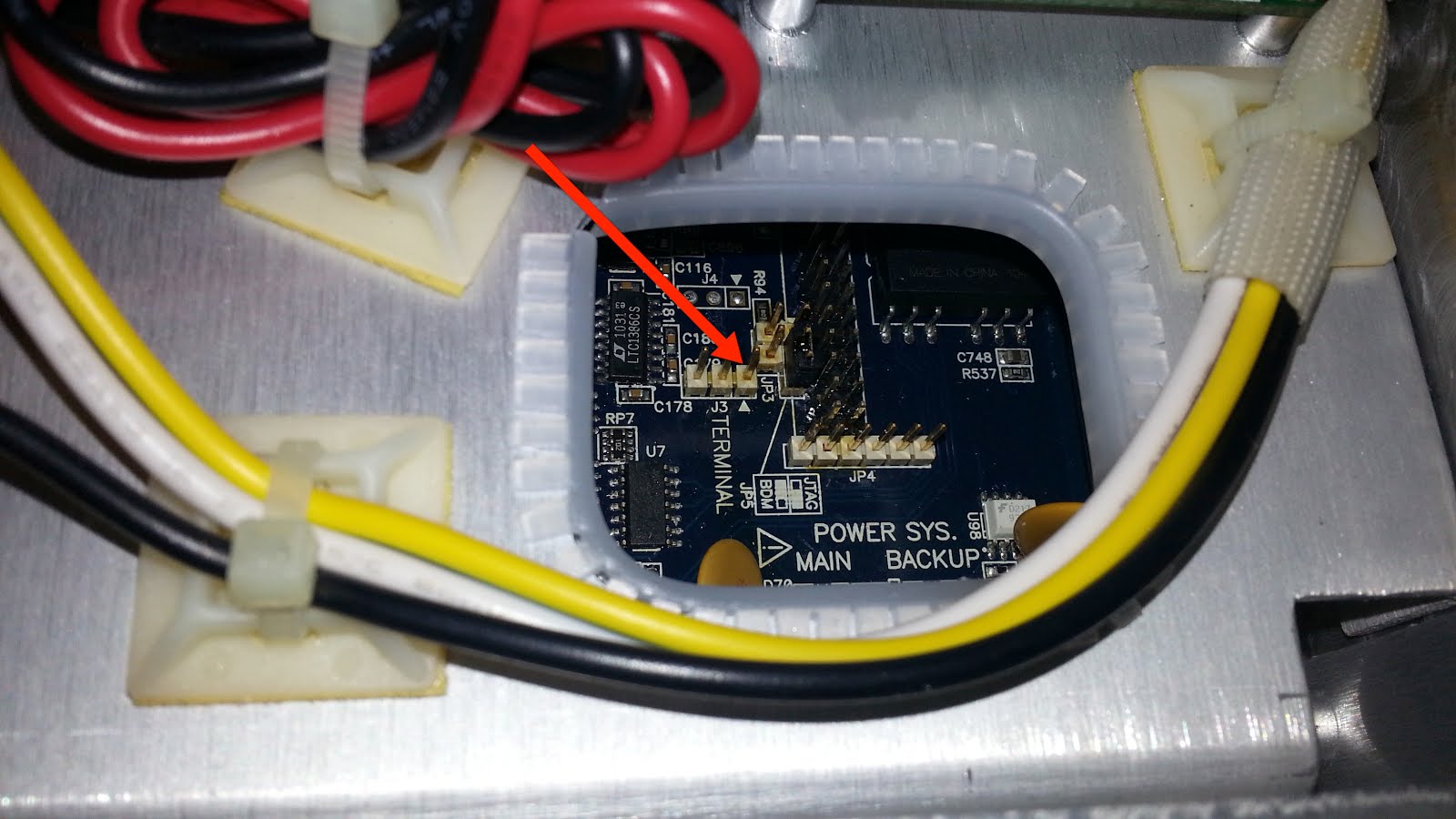
Locate the two sets of Red and Black Power wires that plug into the mainboard. One is for mains power, and one is for back up power. The serial header is located near these connectors and is labeled J3 TERMINAL. Note that the small white triangle indicates PIN 1. The red arrow in this picture is also pointing at PIN 1 of this serial header.
Header Connection
Connect the serial cable noting the orientation of PIN 1 on the header to PIN 1 of your cable. Connect the other end to any standard RS232 serial port on your computer. You can use any serial port program, including Putty, which can be downloaded from here or search the web for "putty".
Session Connection
This picture shows proper settings for using Putty.
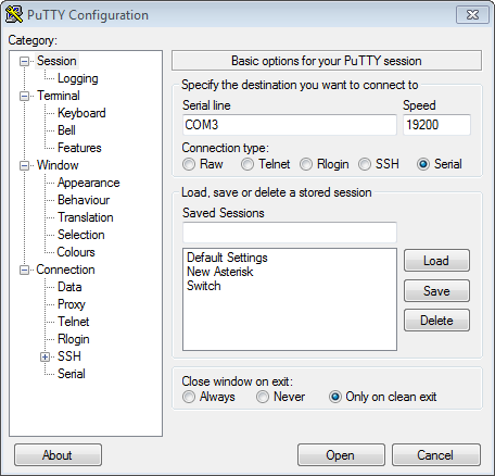
Once you have your cable hooked up to both the QOR and your computer, you can click the Open button on Putty. It should open up a terminal window and probably show you nothing other than a blinking cursor. If a window opens and then quickly disappears after you click Open, you have chosen an incorrect serial port. You can use Windows Device Manager to confirm what serial ports are in use on your computer.
Verification of QOR Operation
Power up your QOR. If you have removed the power connectors to gain access to the serial header, reconnect those and plug the QOR into power. If your QOR is working, you will see the following messages scroll by;
CPU & peripheral init.
Flash autodetect: part id=8821
Init Marvell 88E6095 switch @ 16
MICRO MONITOR 1.16.9
Platform: Cobalt
CPU: Coldfire 5274
Built: Jan 27 2011 @ 18:53:57
Monitor RAM: 0xc00000-0xd081ac
Application RAM Base: 0x200000
MAC: 00:50:C2:80:00:01
IP: 192.168.1.202
BootSelect=0 (hit ESC to enter monitor, BS to skip JFFS.)
JFFS2 partition at 0xff760000, size 0x880000
Current MAC is: 00:50:c2:90:00:66
Current Boot is: bank 2
Booting from partition 3
DEBUG: Partition 3 is at 0xff3c0000
S/W Bank 1.2.0.217 1915991 bytes
Decompressed 3957760 bytes
Linux version 2.6.28 (oleg@orthus) (gcc version 4.5.2 (Sourcery CodeBench Lite 2011.03-97) ) #22 PREEMPT Tue Mar 12 18:48:56 EET 2013
Wait for the scrolling of the message to stop. Generally, it will take less than 1 minute. Once the scrolling of messages stops, you should be able to press the enter key, and you will be presented with a prompt that looks like this;
/ #
You are now at the standard Linux command prompt.
If you have confirmed proper cables and settings and you get no response from the QOR when booting, likely there is a hardware problem, and the unit will need repair.
Also, note that there are built-in GPIO and Audio Loopback testing that can be performed to confirm proper operation of all GPIO and Audio inputs and outputs. This is covered under a separate document and requires a special GPIO tester for testing GPIO and special audio cables for testing Mic inputs. Schematics for these cables are available by following the links to the documents if you have an interest in building them. We do not offer these as pre-built cables.
Let us know how we can help
If you have further questions on this topic or have ideas about how we can improve this document, please contact us.