Using PuTTy to monitor Element Power Supply GPIO
 Updated
by
Bryan Jones
Updated
by
Bryan Jones
Scope
This document covers monitoring of GPIO in an Element GPIO & Power Module using a telnet program, like PuTTY.
Description
Since Flash and Java have no support in most modern browsers it has become increasingly difficult to monitor GPIO. The Element GPIO and Power Module were discontinued before these technologies (Java and Flash) became unsupported and, for this reason, there have been no updates to the Element to address this.
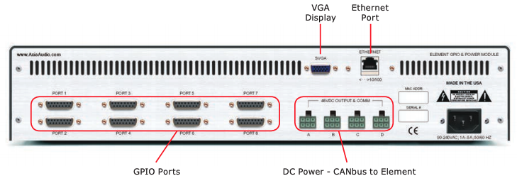
At issue is the monitoring of the eight GPIO ports found on the back of the unit.
Using PuTTy to monitor GPIO
PuTTy is freely available terminal software distributed under the free MIT license. Click HERE to be taken to the download site.
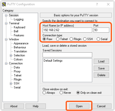
- Launch PuTTY
- Enter the IP Address of the device you want monitor GPIO for. In our example, 192.168.2.62
- Enter Port 93
- For the Connection Type, pick Raw (not Telnet)
- Click Open
A blank terminal window will open. You can press the Enter key a couple of time to confirm you are connected. If you are properly connected you will receive the message ERROR 1000 bad command in the terminal window. This is normal.
Subscribing to changes
In order to see changes to the GP Inputs you have wired, or the GP Outputs controlled by the system, you must "subscribe" to be notified of any changed.
- In the terminal window, type the command (all in CAP)
ADD GPIand press enter. Note there is a space between the words ADD and GPI.
The window will echo the current states of all eight ports GP Inputs in this format.
BEGIN
GPI 1 hhhhh
GPI 2 hhhhh
GPI 3 hhhhh
GPI 4 hhhhh
- GPI - indicates these are the input pins.
- 1 thru 8 - these are the physical 15-pin ports on the back of the unit.
- hhhhh - status of all five inputs (or output) pins.
A word about pin status. All five pins are reported for each port. If the FIRST input you wired is activated, the report is Lhhhh. Note the capital L. Capital letters represent the transition to the new state. Meaning, if input number one is active you get Lhhhh. If input one remains active and then input two is activated, you would see lLhhh. The lower case "l" at position one, indicates that bit was already low when bit 2 transitioned to the low state.
For a momentary relay on input one, you would see Lhhhh followed by Hhhhh.
L (LOW) represents the "relay closed" state. As if you were holding your finger on the button.
H (HIGH) represents the resting state of the input.
- Repeat this step if you want to monitor GPO (GP Outputs) as well. Type
ADD GPOand press enter. The same rules for indication apply to the GPO as for the GPI.
Let us know how we can help
If you have further questions on this topic or have ideas about improving this document, please contact us.