Internal cables used for connecting Quasar modules
 Updated
by
Bryan Jones
Updated
by
Bryan Jones
Scope
Each Quasar module requires an internal network and (possibly) dual power connection. This document details the part numbers of the cables that are used for this.
Description
Each Quasar 4-Fader and Master Touch Screen Module has two network connections and two power connections. Network connections are used to connect from one module to another. The Power connectors are needed to supply power to the module. If you have multiple Power Supplies in your Quasar, the power distribution boards are internally bussed together for redundancy. To prevent damage to the modules or power supplies, do not connect more than one power distribution board to each module. The second power connector on each module may be used to connect power a second module.
Cables
Network Cables and their part numbers
- Part number 1711-00479 - 1 FT- Right angle connector on ONE end. Connects the first and last module to the frame. Do not use to connect from module to module. The connector can impact the bottom fo the Quasar frame damaging the cable and/or the module. (currently BLUE)
- Part number 1711-00480 - 1 FT - right angle to right angle ethernet cable. Used to connect from module to module. (currently Beige)
- Part number 1711-00481 - 3 FT - right angle to right angle ethernet cable. Used to connect from module to module. (currently Beige)
- Part Number 1711-00482 - 5 FT - right angle to right angle. Used to connect module to module
Quasar Power Distribution Board to Module Internal 4-pin power cables and part numbers
- Part number 1711-00429 - 12 in
- Part number 1711-00441 - 24 in
- Part number 1711-00455 - 36 in
- Part number 1711-00488 - 48 in
Quasar Power Supply to Power Distribution board cables and part number
- Part number 1711-00452 - 12 in (300 mm)
- Part number 1711-00453 - 24 in (600 mm)
- Part number 1711-00486 - 36 in (900 mm)
- Part number 1711-00487 - 48 in (1200 mm)
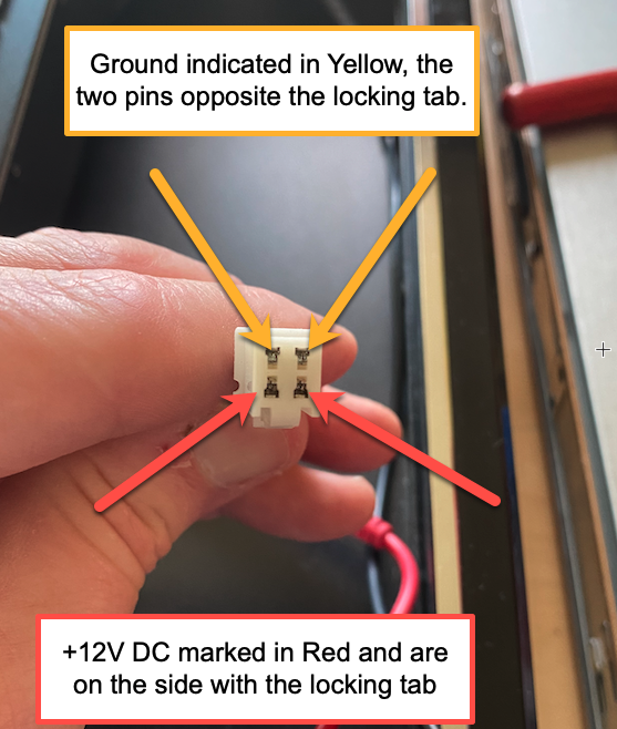
Pinouts for the cables from the Power Distribution Board (PDB) to the modules are as follows. Note the connector orientation. Locking tab oriented down. The connector is facing as if you were connecting it to the receptacle.
Bottom Left and Right pins are +12 volts DC.
Top Left and Right pins are chassis ground.
Let us know how we can help
If you have further questions on this topic or have ideas about how we can improve this document, please contact us.