Setting up and using IPump 8640 for Livewire
 Updated
by
Tony Dimsdale
Updated
by
Tony Dimsdale
Scope
This document covers the setup of the West Wood One IPump 8640 receivers for Livewire. Note that not all West Wood one receivers can be used for Livewire.
Configuration
Network Configuration
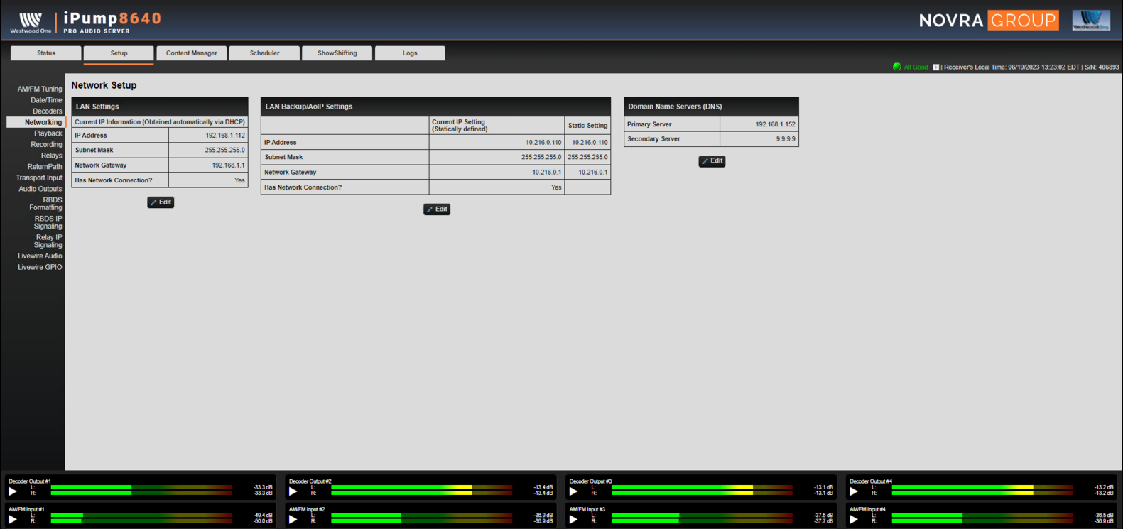
- From the Setup Tab, choose the Networking Menu option and enter you AOIP networking Info. IP Address, Subnet Mask and Default Gateway. Choose Update:
Audio Configuration
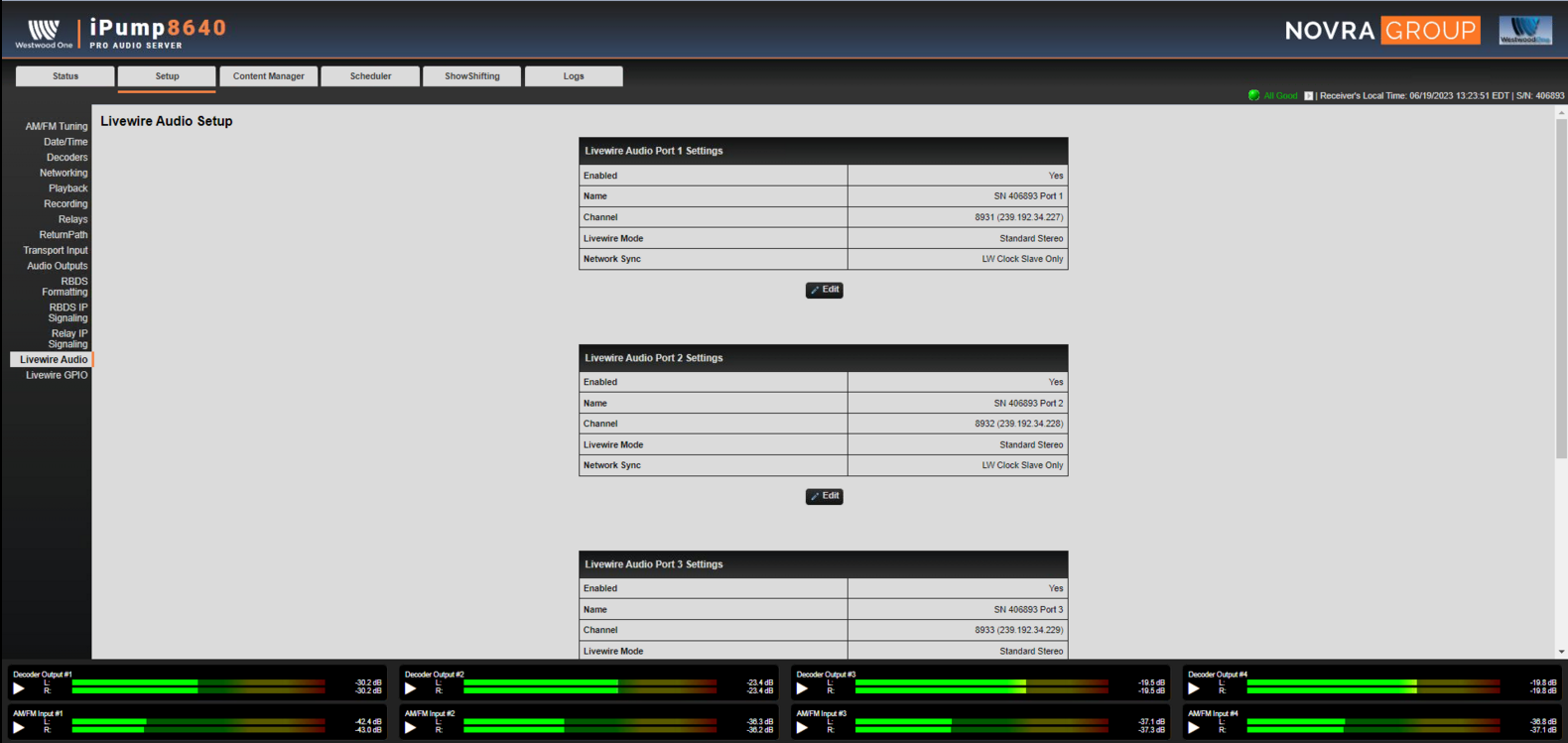
- From the main Web Page, click on the Livewire Audio link. You will see the 4 Stereo Channel Outputs.
- Each channel will need to be enabled, the default LiveWire Channels are 8931-8934. These can be changed to match your network if needed, choose the Edit button. Edit and choose the Update button for each output.
- Set Enable Livewire to ON. The configuration options change to Livewire specific settings when setting to ON.
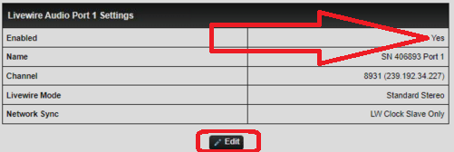
In the Livewire Audio section, set a friendly Name, Channel number, & Mode.
- Name - Any name to help describe the source in your system.
- Channel number - A unique Livewire channel number
- Mode - Standard Stereo is an appropriate choice. Live Stereo is only required for a microphone to headphone path. Sources from the receiver will not require Live Stereo.
GPIO Configuration
GPIO has some special considerations.
The IPump 8640 Model uses a relay mapping method for the relays. Usually this would be left default using a 1 to 1 mapped relay. This can be modified, to do so, we recommend speaking with West Wood Support first.
- From the main Web Page, click on the Livewire GPIO link. You will see the 4 GPIO Channel Outputs. By Default, the GPIO LiveWire Channels are tied to the LiveWire Audio Channels.
- Each channel will need to be enabled, the default LiveWire Channels are 8931-8934. These can be changed to match your network if needed, choose the Edit button. Edit and choose the Update button for each output.
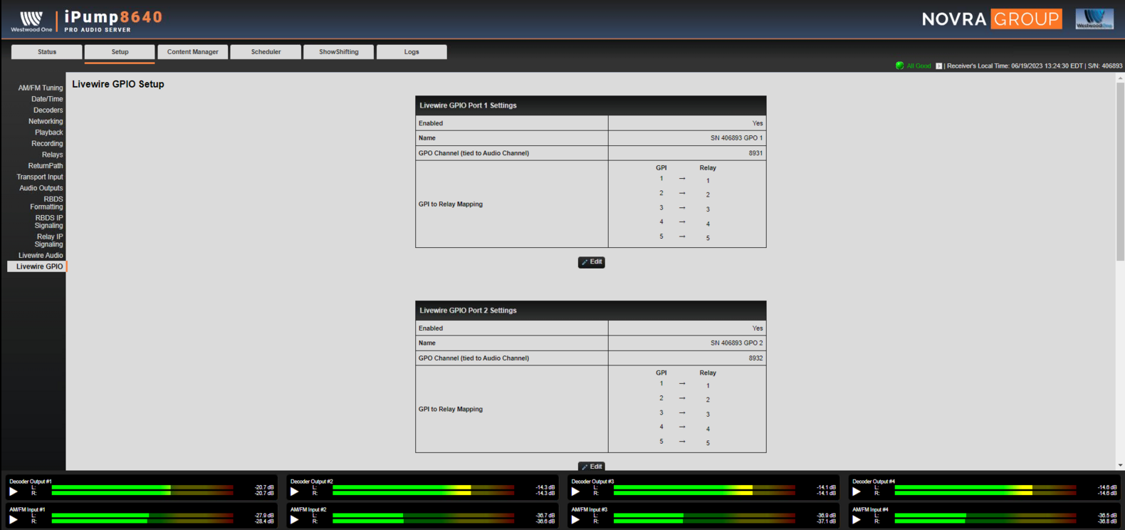
In the Livewire GPIO section, set a friendly Name, Channel number, & Relay MAP
- Name - Any name to help describe the source in your system.
- Channel number - A unique Livewire channel number
- Relay Map - Standard mapping is an appropriate choice. Special mapping is only required for special use case for the relays. Speak to West Wood One support before making changes to this section. .
Using the receiver in your network
Using Audio
Selecting audio directly in a Livewire DST (Destination)
Using audio is just like any other source in your network; channels advertise like normal. Naming your Livewire channels and your receiver will help identify them in your system. In addition to the channel names assigned above, by default the receiver name is set to "SN 406893 Port 1" on the LiveWire Audio page. You can see our channels advertised as SN 406893 Port 1@ipump406893.
Add to Pathfinder
Once Livewire is enabled, you can add this receiver to Pathfinder. The audio sources are available to the rest of the system for Routing.
- In Pathfinder Core PRO, click the Devices link on the main Web Page.
- Click the
 sign at the bottom right of the devices list
 - In the Address to Investigate window, add the IP address of your IPump receiver. Click Investigate.

This will add your Ipump Receiver to both the AUDIO and GPIO routers in Pathfinder Core PRO. Once added, sources from Ipump can be routed just like any other source in your system.
Add Channel to an XNode
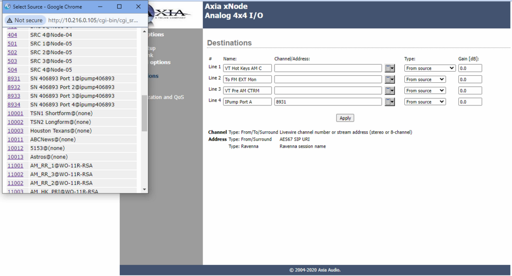
- To add the device to your Xnode, Choose the IPump Port LiveWire Channel from the Discovery tool under teh Destinations Page of your Xnode. This will add the Audio Channel to your Xnode.

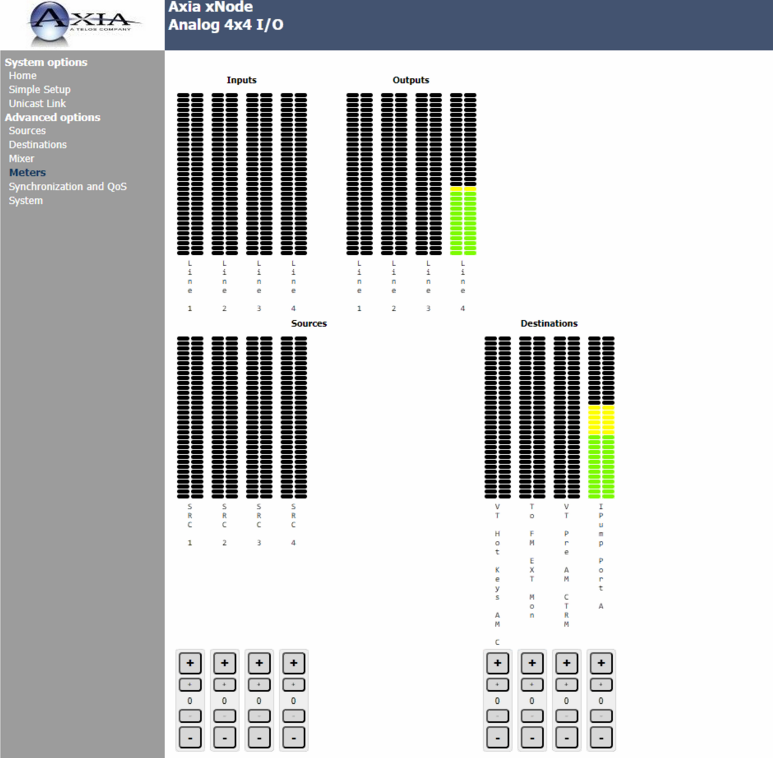
- You may then see your audio under the meters page on the Xnode. Adjust levels or mix the audio in the mixer page with other DST on your network.
Using GPIO
Mapping Ports in the Axia IP Audio Driver
In the Axia IP Audio Driver, we can "map" the ports in the Driver to the ports on the receiver. Mapping these ports (also referred to as GPIO Routing) allows the GPIO pins to be received locally on the Driver for use by your automation system. Use this method if your automation system can only see GPIO from a local device. Contact your Automation System vendor for the specific capabilities.
To map channels in the Driver;
- Open the Driver configuration program from Windows Control Panel.
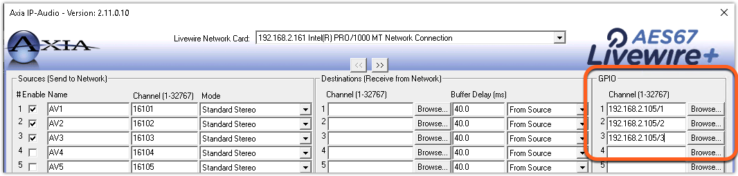
- To "map" the GPIO in the WW1 Receiver to your Driver, enter the
ipaddress/portof your WW1 Receiver. In our example, 192.168.2.105 is the IP address of the receiver, and ports 1, 2, and 3 are mapped to channels 1, 2, and 3 of the Driver. You do not need to map these one-to-one. You can map any GPIO port in the Driver to any port in the receiver. Once mapped, the pins are brought directly to the Driver. Pin 1 on the WW1 is pin 1 on the mapped channel of the Driver. Pin 2 is to Pin 2 on the Driver. Pin 3 to 3, etc.
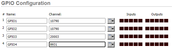
Mapping Ports in a Xnode, QOR or PowerStation
- Login into the device naviagte to the GPIO Section of the device. Type in your LiveWire GPIO Channel number on the port you would like to assign the GPIO too. You can monitor the GPIO here as well, the light will illuminate green when the pin is set to LOW.
Let us know how we can help
If you have further questions on this topic or have ideas about improving this document, please contact us.