Evaluating Ethernet Switches for AoIP
- Scope
- The Ethernet Switch:
- Facility Network Topology:
- IGMP
- QoS
- Notes about switch port configuration
- Notes about Power Handling
- Switch and Network Performance Testing
Scope
This doc will outline the steps to follow in evaluating an AoIP switch if you choose to use one that is not included in our doc
The Ethernet Switch:
The backbone of any corporate, private, or home network. In the AoIP world, the Ethernet Switch is responsible for managing the packets that make up the audio streams distributed to all of the devices on the network. Livewire operation relies on the network design and behavior, which is largely determined by the features and configuration of the switches used. In this paper, we will discuss these functions and how to evaluate a switch that is being considered for use with Livewire.
Any switch that can be configured to behave correctly for the fundamentals of AES67 AoIP is acceptable. Remember that switches must be able to handle hundreds of thousands or millions of packets per second. The switch must be high quality, it must support hardware speed switching and must be reliable. The technical support staff at Telos have formal training for supporting switches made by Cisco. So even though many switches fit this criterion, the syntax we will be referencing in this paper comes from the Cisco command line.
Facility Network Topology:
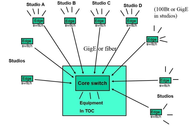
In this document, the terms “Core” and “Edge” switch are used. The network topology assumed by the use of IGMP multicast routing is a branching tree hierarchy, with the core at the trunk and edge switches are plugged into the core. (see the illustration below)
A simple core and edge switch topology has valuable properties for broadcast. If the core switch goes down, the individual studios can stay on the air by providing basic connectivity from the studio. If any of the studios go down, the facility is symmetrical so you can broadcast from another studio. Redundant edge to core network connections and dual redundant core switches can be used.
Other network topologies such as mesh or extended chains without a central core point to serve as IGMP root querier will have to be designed, configured, tested, and verified with attention being paid to the proper operation of multicast routing, QoS (where it applies), and PTP (where it applies).
There are two pillars of AoIP network behavior: IGMP and QoS. IGMP manages the subscriptions devices have to streams that are available on the network while QoS assigns audio packets the highest priority for minimum latency on the network. The next sections of this paper will discuss these functions. We will go over how to program them using the Cisco command line and how to test their functionality.
IGMP
Internet Group Management Protocol, or IGMP, is a function we use to manage the streams being handled by the switch. When a device subscribes to a stream, it is the function of the IGMP querier to ensure that the stream is being delivered. When a device unsubscribes (stops requesting) from a stream, the switch acting as the IGMP querier will stop sending the multicast stream to the port. This stops the network from flooding because of rouge streams and keeps audio from dropping out. In the configuration we are discussing, all of the switches in the network have the ability to become the IGMP querier. This ensures that the network still has an IGMP querier should the core switch go down. In the case where the edge switches lose their connections to the core switch, each studio will have its own IGMP querier until the core switch is restored.
For example, the instructions used in the Cisco WS-C2960S command line are as follows:
config t
ip igmp snooping querier max-response time 25
ip igmp snooping querier vlan 1 immediate-leave
ip igmp snooping querier
ip igmp snooping querier timer expiry 205
end
- “
Config t” tells the interface to enter the configuration terminal where the user can enter commands into the root of the switch. - The first “
ip” command sets the maximum response time when this switch becomes the IGMP querier. - The second “
ip” command tells the switch to immediately shut off the multicast group with an "IGMP Leave" message is received. This stops the old audio channel from being sent when an audio route change is made. - The third “
ip” command simply allows this switch to become the querier. (In Cisco networks where this is active on multiple switches, the switch with the lowest IP address in the subnet becomes the querier) - The fourth “
ip” command sets the timeout. If no IGMP query messages are seen on the network, assume this switch becomes the querier. - Finally, “
end” tells the terminal that there are no more instructions.
ip igmp snooping querier.” The message may say certain functions are not enabled. This is OK, you can disregard these messages.We will go over testing this functionality a little bit later, so stay tuned. Before we do, let’s talk about prioritizing packets.
QoS
Quality of Service, or QoS, is a tag on the audio packet that guarantees priority delivery throughout the network. All other traffic takes a backseat to audio packets. This is to keep audio passing through the network without delays during instances of high network traffic from HTTP, FTP, or other activity (Video Streaming, perhaps). Of course, if the network switch has enough headroom in its bandwidth specification, QoS prioritizing may not be necessary. When in doubt, use it. In our recommended configuration, at least 3 priority queues are used. Set roughly equal sharing of bandwidth to outgoing queues that are not strict priority. In the Cisco WS-C2960S command line, the following is used:
config t
mls qos srr-queue output cos-map queue 1 threshold 1 6 7
mls qos srr-queue output cos-map queue 3 threshold 1 5
mls qos
end
- Again, “
config t” enters the configuration terminal. - The first "
mls qos" command maps the COS* levels 6 and 7 (layer 2 tagged Vlan priority tag) to output queue 1. In this switch, only output queue 1 may be set to strict priority mode, which is what we want for low latency (250µs packet) audio and clock sync packets. - The second "
mls qos" command maps the COS* level 5 to output queue 3. This switch has 4 output queues. The other three queues are round robin only. Put COS* 5 which is large packet audio (4ms latency) into its own queue to avoid starvation. - The last "
mls qos" command enables QoS. (QoS is not enabled by default in Cisco) - Once again, “
end” tells the interface that we are done giving it instructions.
We will also go over testing this function. Before we do, a few words about switch ports.
Notes about switch port configuration
Setting up interfaces to be Trunk or Access is beyond the scope of this document. Depending on what switch you are evaluating, care must be taken to ensure that the ports being used have the proper configuration. As a general rule, ports that connect network appliances such as routers and other switches together must be configured as Trunk. This includes connections to the Axia QOR and PowerStation engines because the Ethernet ports on those devices are parts of an internal switch. Interfaces that connect things like nodes and computers to switches must be configured as Access.
Care must be taken to ensure each port is configured properly. There are several different documents showing how to do this with a myriad of Cisco switches on the Axia website. The manufacturer of the switch should also be able to provide guidance regarding the setup of Access and Trunk ports.
Notes about Power Handling
Energy Efficient Ethernet (EEE), IEEE 802.3az, is a standard that allows network devices to dynamically control power consumption based on the link status. The IEEE 802.3az standard was ratified by the Institute of Electrical and Electronics Engineers in 2010, but even prior to the standard ratification switch manufacturers were implementing environmentally friendly operating modes. When considering selecting switches for an AoIP installation ensure the switch manufacturer provides an option to disable Energy Efficient Ethernet, or said manufacturer's proprietary environmentally friendly operating mode. EEE will need to be disabled in order to optimize the performance of the network.
In the Cisco 9000 series, this command is used to turn this off in Trunk configurations:
no power efficient-ethernet auto
Switch and Network Performance Testing
In our evaluation, we will test that IGMP and QoS are performing properly. We will test these two functions in a few different contexts, starting with a basic 1-switch setup and moving all the way to redundant edge switches with dual core connections.
Level 1 Testing: One Switch with Two Nodes
Test 1.1, Verify QoS is working properly :
Livestream and clock packets not delayed by non‐audio (html) traffic.
- Equipment: Two Livewire nodes, two computers, connected to the switch under test.
- Goal: Determine that the QoS mechanism of the switch is correctly prioritizing the IP packets marked higher priority.
- Pass criteria: When heavy data transfer is made between the two computers, no audio defects are heard, no sync light starts to blink, and no audio overrun or underruns are counted in the Livewire nodes.
- Fail criteria: When data transfer is made between computers, either audio defects are heard, the sync light starts to blink, or audio overrun / underruns are counted in the Livewire nodes.
Test procedure:
- Set the Livewire nodes to transfer audio in Livestream mode (low latency mode) in both directions, from A to B and B to A.
- Run live audio in both directions, preferably low frequency pure test tones, like 220Hz sine waves, for which it is easy to hear audible clicks, pops or other defects.
- Using telnet, log into the Livewire nodes and use the command ‘lwrd –stat’. Note the count of OR and UR (Overruns and Underruns) in columns corresponding to the rows of the audio channels. These may not be zero which is a normal part of initiating audio channel connections.
- While the audio is running, transfer a large amount of data between the two computers, or between one computer and a server. (file transfer or file upload or download).
- Listen for audio defects during the time of the data transfer.
- Rerun the telnet ‘lwrd –stat’ command on both nodes and confirm that the count of UR or OR did not increase during the data transfer test.
Test 1.2, Verify IGMP is working properly :
Not flooding: Audio & clock not coming out other ports of switch.
- Equipment: Two Livewire nodes, one computer with packet sniffing software ‘Wireshark’ or equivalent, connected to the switch under test.
- Goal: Determine that the multicast routing mechanism of the switch is operating properly, and multicast packets are only being routed to the ports that are requesting the multicast addresses.
- Pass criteria: There are no audio or clock packets coming out of the ports of the switch that are not connected to the Livewire nodes.
- Fail criteria: There are audio or clock packets coming out of switch ports that are not connected to the Livewire nodes.
Test setup:
- Set the Livewire nodes to transfer audio in Livestream mode in both directions, from A to B and B to A.
- The audio content does not matter for this test. Any audio, or silence is acceptable.
- Connect the computer with the packet sniffing software to one of the open ports of the switch.
- Using the packet sniffing software, verify that none of the audio packets or clock packets are coming to sniffing port. Audio packets are easily identified by the high rate of multicast packets.
- Check each of the open ports on the switch, including the trunking ports. With IGMP properly configured, multicast should not go to the trunking ports without a core switch connected also configured to the the IGMP multicast querier.
Level 2 Testing: Edge Switch with Core Switch
These tests are designed to confirm that the switch functions properly in conjunction with a core switch in a hierarchy.
Test 2.1, Verify QoS working is properly :
Livestream and clock packets not delayed by non‐audio (html) traffic, with high traffic load with the core switch.
This test is similar to test 1.1, except that the audio and non‐audio traffic go through the arrangement of 3 switches, edge, core and edge.
- Equipment: Two Livewire nodes, two computers, one Livewire qualified core switch, two edge switches.
- Goal: Determine that the QoS mechanism of the edge switch is correctly prioritizing the IP packets marked higher priority being sent out their trunk ports. Also that the QoS tags on packets are compatible between the core and edge switches.
- Pass criteria: When data transfer is made between the two computers, no audio defects are heard, no sync light starts to blink, and no audio overrun or underruns are counted in the Livewire nodes.
- Fail criteria: When data transfer is made between computers, either audio defects are heard, the sync light starts to blink, or audio overrun / underruns are counted in the Livewire nodes.
Test configuration:
- Arrange the network as two edge switches connected to the core switch.
- Connect the Livewire audio nodes to two different edge switches.
- Configure the core switch to be IGMP Querier.
- Configure the ports of the edge switches connecting to the core, are set to trunking mode. (Trunking mode means all multicast traffic is sent towards the core).
- Configure the QoS settings of the core and edge switches to be compatible.
Test procedure:
- Set the Livewire nodes to transfer audio in Livestream mode (low latency mode) in both directions, from A to B and B to A.
- Run live audio in both directions, preferably low frequency pure test tones, like 220Hz sine waves, for which it is easy to hear audible clicks, pops or other defects.
- Using telnet, log into the Livewire nodes and use the command ‘lwrd –stat’. Note the count of OR and UR (Overruns and Underruns) in columns corresponding to the rows of the audio channels. These may not be zero which is a normal part of initiating audio channel connections.
- While the audio is running, transfer a large amount of data between the two computers, or between one computer and a server. (file transfer or file upload or download). Have the computer to computer (or computer to file server) connection go from one edge switch to the other edge switch.
- Repeat test 4 with one computer connected to the core switch and one connected to one edge switch.
- Listen for audio defects during the time of the data transfer.
- Rerun the telnet ‘lwrd –stat’ command on both nodes and confirm that the count of UR or OR did not increase during the data transfer test.
Test 2.2, Verify IGMP snooping Querier Handoff :
When edge switch connected to core switch, the core becomes the IGMP querier. When the edge switch is disconnected from core switch, the edge switch becomes the IGMP querier. When the core is reconnected, the IGMP querier should move back to the core switch.
- Equipment: 4 Livewire nodes, two computers, one Livewire qualified core switch, two edge switches.
- Goal: Determine that the IGMP querier moves from the core switch to the edge switch, and back. This is to prove that the studio’s containing an edge switch will continue to function properly independent of the core, if the network connection to the core is lost. This is an important redundancy feature for keeping studios on the air in the case of certain network equipment failures or human error.
- Pass criteria: Audio and sync operation continues normally when the connection to the core switch is lost. No loss or distortion of audio, no persistent sync light blinking, and no multicast flooding occurs in the edge or the core.
- Fail criteria: When the connection to the core switch is interrupted, audio loss or distortion occurs or sync light blinking persists. When reconnecting to the core switch, the core does not become IGMP querier again, and all multicast traffic is sent from core to the edge, or multicast flooding at the core or edge.
Test configuration:
- Arrange the network as two edge switches connected to the core switch.
- Connect 2 Livewire audio nodes A and B to one edge switch that is under test. Connect the 3rd livewire node D to the other edge switch. Connect the 4th node C directly to the core switch.
- Configure the core switch to be IGMP Querier (lowest IP or MAC address).
- Configure the ports of the edge switches connecting to the core, are set to trunking mode. (Trunking mode means all multicast traffic is sent towards the core).
- Configure the QOS settings of the core and edge switches to be compatible.
- Connect the computer with packet sniffer to the edge switch under test.
Test procedure:
- Set the 4 Livewire nodes to transfer audio in Livestream mode (low latency mode) in both directions, from A to B, A to C, A to D, B to A, B to C, B to D, etc and the reverse. All 4 nodes streaming to and from the other nodes.
- Run live audio in both directions, preferably low frequency pure test tones, like 220Hz sine waves, for which it is easy to hear audible clicks, pops or other defects.
- While the audio is running, interrupt (unplug) the connection from the edge switch that has 2 livewire nodes connected to it, to the core switch.
- Verify the audio stops which comes from the node on the other edge switch.
- Verify the audio is not interrupted or distorted between the two nodes on this edge switch.
- There may be a Livewire master transition. If one of the two nodes on the edge switch under test was not master, one of them will become clock master (MASTER mode comes on.) The other node SYNC may blink momentary as it settles to the new master but should then go solid SYNC in less than a minute or two.
- Verify with the packet sniffer that audio packets are not coming out the other ports on the edge switch under test. This means that this edge switch is not flooding and has successfully become IGMP querier.
- Continue to monitor for flooding for 5 minutes. Some decisions made by IGMP logic take some time to time out.
- Reconnect the edge switch to the core switch.
- Verify the audio connection comes back between the nodes spanning across the core.
- Verify no audio loss or distortion in all of audio paths.
- Verify no flooding with packet sniffer on edge switch port.
- Verify no flooding with packet sniffer on core switch port.
- Use the diagnostic monitoring feature of the core switch to check the amount of traffic going to the edge switch under test. The amount of traffic should correspond to only two audio channels, that is one channel from C and one from D. Each Live stream is approximately 5Mbit/s, so the total should be 10Mbit/s. If the amount of traffic is larger, this can indicated that the core switch did not become IGMP Querier, the edge switch continues to be IGMP Querier, and the core is incorrectly sending all multicast traffic to the edge switch including audio channels between C and D which are not supposed to go to A or B. Optionally use the diagnostic interface to verify the core switch is the IGMP querier.
Test 2.3, Verify proper operation recovers when edge switch is power cycled :
When the edge switch is power cycled, the edge switch must come back online and properly interact with the running core switch and accept audio multicast traffic as it initializes.
- Equipment: 4 Livewire nodes, two computers, one Livewire qualified core switch, two edge switches. (Same as prior test 2.2)
- Goal: This is to prove that the studio’s containing an edge switch will wake up, initialize, and function properly while connected to a running system.
- Pass criteria: Audio and sync operation restores normally when the edge switch is power cycled. Audio comes up, no distortion of audio, sync light stabilizes, and no flooding occurs in the core or edge.
- Fail criteria: Audio does not restore, or audio distortion occurs or sync light blinking persists, or multicast flooding.
Test configuration:
- Arrange the network as two edge switches connected to the core switch.
- Connect 2 Livewire audio nodes A and B to one edge switch that is under test. Connect the 3rd livewire node D to the other edge switch. Connect the 4th node C directly to the core switch.
- Configure the core switch to be IGMP Querier (lowest IP or MAC address).
- Configure the ports of the edge switches connecting to the core, are set to trunking mode. (Trunking mode means all multicast traffic is sent towards the core).
- Configure the QOS settings of the core and edge switches to be compatible.
- Connect the computer with packet sniffer to the edge switch under test.
Test procedure:
- Set the 4 Livewire nodes to transfer audio in Livestream mode (low latency mode) in both directions, from A to B, A to C, A to D, B to A, B to C, B to D, etc and the reverse. All 4 nodes streaming to and from the other nodes. (Same as previous test 2.2)
- Run live audio in both directions, preferably low frequency pure test tones, like 220Hz sine waves, for which it is easy to hear audible clicks, pops or other defects.
- While the audio is running, power off the edge switch under test.
- Power on the edge switch.
- Verify the audio restores in all connections, in both directions.
- Verify the audio between nodes C and D (core and other edge) does not get interrupted.
- Verify the audio is not distorted in all connections.
- Verify with the packet sniffer that audio packets are not coming out the other ports on the edge switch under test. This means that this edge switch is not flooding.
Test 2.4, Verify proper operation recovers when core switch is power cycled :
When edge switch connected to core switch, the core is the IGMP querier. When the core switch is power cycles, the edge switch becomes the IGMP querier. When the core reconnects online, the IGMP querier should move back to the core switch.
The setup, goals and procedure for this test are the same as test 2.2. The only difference is instead of unplugging the cable from the edge to the core, power the core off and back on.
Level 3 Testing: Redundant edge switch to dual core connection
A system with redundant core connection is first tested in the same way as a non redundant core. Follow all level 2 tests, above.
In addition, there are some additional tests to verify. Use the same setup as Level 2.
Test 3.2, Verify duplicate set of packets is not being transferred :
A mis-configured redundant core connection can create duplicate packets being received. Duplicate packets can create audio distortion, and measured as twice the network traffic where only one set of audio streams is supposed to be present.
Test 3.3 Verify redundant connection switch over :
This tests that redundancy is actually functioning as intended. Disconnect one connection from switch to core, verify the network switch-over, without loss of audio. Reconnect first connection, disconnect second connection: verify normal audio without flooding.
Test 3.4, Power cycle one core, recover, then alternate core power cycle :
This is closely related to test 4.3, but rather than testing for redundant switching with the disconnection of a link, this tests for the power loss and recover of each core.
Verify normal audio system continues operation on one core, and then recovers without flooding.