iQx Surface - Using Test Mode
Before we begin
Please take the time to read through this document before starting any work. The iQx system has a built-in self-test for performing diagnostics on surface hardware. Disconnect all cabling and power from the unit prior to proceeding. You will be exposing very sensitive components to the outside world, so please take special care to work in a static and moisture-free environment. Field upgrades and repairs are performed at your own risk, so please take care. If you would rather send the unit to the factory for service, contact Telos Technical Support and request a Return Authorization.
Equipment Needed
- Device Under Test (DUT): iQx Console
- Power Supply - Line-lump style supply, Telos part 1281-00174-100
- Phillips Screwdriver
- Small needle-nosed pliers - or tweezers
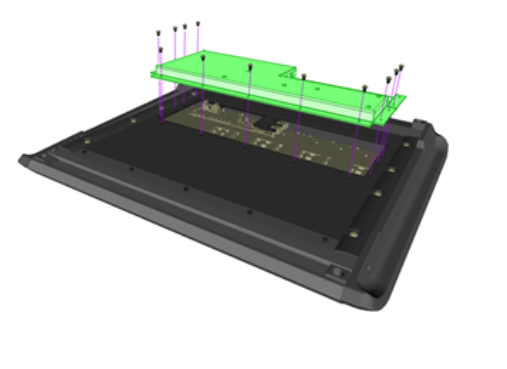
Remove Bottom Dress Panel
Turn iQx upside down and place on a soft surface in order to have access to the underside. Remove the (13) screws from the bottom dress panel show here.
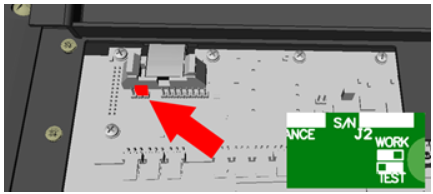
Control Surface Test Jumper
On the control board near the IDE connector for the overbridge, you will find the test mode pins. Set the jumper to the TEST position. The center pin is connected to the right hand pin in TEST mode:
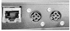
Apply Power and Verify
Connect the power supply to one of the circular panel mount connectors. Be careful not to let any of the dress panel’s metal surfaces come in contact with the PCBs.
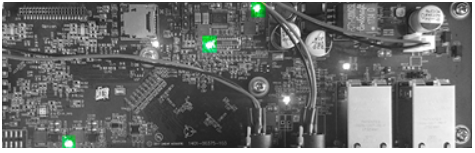
Verify that the main CPU board mounted onto bottom panel has stable green LEDs illuminated as shown. This will indicate proper power supply operation without failure.
Reattach Dress Panel and Test
Carefully apply the bottom panel back into place and secure some or all the screws.
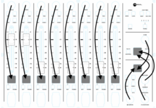
Turn the unit right side up and press all buttons to illuminate the buttons and the displays. Move the far left faders to the appropriate position to illuminate the buttons and displays.
Note the test mode lives close to system code, so it will refer to the fader for channel 1 as “fader 0” and the program 1 button for channel 1 as “button 0” and so on.
Fader Test
Fader-0 movement controls the brightness of the panel buttons while Fader-1 movement controls the brightness of the displays. Slide each fader between its two positions, bottom to top, and observe the fader position value on the associated display.
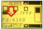
The value expressed on the display is a hexadecimal value. At the minimum setting, the value on the display should be 0020 (+/-35). At the maximum setting, the value on the display should be 7FFE (+/-35).
Button Test:
Move Fader-0 to the maximum top position. Press each button once, when the button is pressed, it will illuminate. With all buttons illuminated, slide Fader-0 to the bottom position. Observe the brightness of all buttons change to no illumination. Return Fader-0 to top position and all buttons will be fully illuminated. Press each button once more to remove the illumination of the button.
Rotary Encoder Test:
Each encoder is displayed in hexadecimal value on a display, under the “Rt:” label. Two sets of encoders are display on single displays. Clockwise rotation will increment the value. Counter-clockwise will decrement the value.
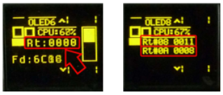
Rotate each encoder clockwise and verify correct value change in the associated display. Reverse rotation direction and verify appropriate value change.
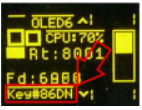
Each encoder has a button function. Pressing the encoder will result in a reported button press on all displays “Key#nnDN”. Press each encoder and verify button DN and UP state are reported.
The OLED displays to monitor during this test are outlined here:
Display Test:
Press Button 00 to invert the displays. Verify response. Press Button 01 to illuminate all pixels on the displays. Inspect displays and make sure there are no missing pixels.
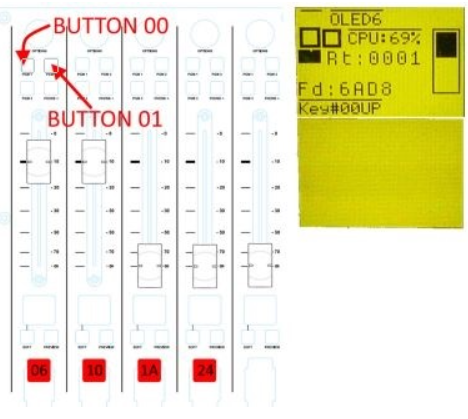
LED Test:
Press buttons 06, 10, 1A,24 (the leftmost four ‘ON’ buttons). With each button press, the green LEDs to the right of the surface will illuminate. Verify all four green LEDs illuminate.
Exit Test Mode
Remove power from the console. Follow the instructions in the beginning of this guide for removing the bottom dress panel and this time move the test mode jumper back to its original positions. Re-attach the bottom panel and re-apply power to restore functionality.
Let us know how we can help
If you have further questions on this topic or have ideas about improving this document please contact us