Assigning individual Microphone GPIO in an IQ Console
 Updated
by
Bryan Jones
Updated
by
Bryan Jones
Scope
This document covers the assignment of GPIO for individual microphones to the physical GPIO ports on the back of the QOR console engines used for iQ Consoles.
If you are looking for the configuration of a generic "on-air" light for the QOR. Please see our document Setting up an On-Air light.
Description
Individual GPIO is used for both control and indication. Examples of use include:
- Individual status lights usually found on each microphone stand.
- A dedicated hardware "cough" button.
- Remote buttons for on, off, and talkback.
- Numerous others (use your imagination).
There are two types of GPIO on the QOR Engine:
- Local sources - those connected to the physical inputs on the back of the QOR engine.
- Livewire sources - those that originate elsewhere on the network.
No matter the origin, the Source Type defines the function of the individual GPIO pins. Click the links below for more information on each type.
Control Room - This is the room where the physical console is located. Microphones in this room mute the Control Room speakers when turned on.
Studio - This usually a dedicated talk studio that is separate from the room where the console is installed. Microphones in this room mute the Studio Monitors, but NOT the Control Room monitors.
- Axia GPIO for Operator Microphone Source types
- Axia GPIO for Control Room Guest Mic Profiles
- Axia GPIO for Studio Guest Mic Profiles
GPIO for local sources
Use this setup when your sources are connected DIRECTLY to the QOR and are NOT Livewire sources. In this configuration, GPIO is applied only to LOCAL sources. You cannot assign remote GPIO to sources locally connected to the QOR Engine.
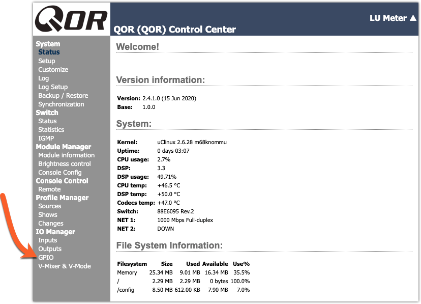
- Using a Web Browser, click on the GPIO link under the IO Manager heading.
- Assign a friendly Name. GPIO 1 is Operator Mic, GPIO 2 is Studio Mic 1, and GPIO 3 is Studio Mic 2. These names are for ease of identification only.
- Assign Logic For. Pick "Logic for" based on the physical port on the back of the QOR where you plugged in your device. In our example, the Operator Microphone is connected to Microphone input 1 on the back of the QOR. Studio Mic 1 is physically connected to Microphone Input 2. Etc.
- Leave the Livewire Channel set to 0.
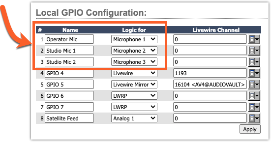
- Click Apply
GPIO is automatically applied and is active no matter what fader of the console is used. This configuration allows the flexibility to assign Microphone 1 to any fader, and the GPIO will automatically follow.
GPIO for Livewire Sources
Use this setup when your sources originate via Livewire and are NOT connected to a local port on the QOR Engine.
- Using a Web Browser, click on the GPIO link under the IO Manager heading.
- Assign a friendly Name. In our example, GPIO 1 is Operator Mic, GPIO 2 is Studio Mic 1, and GPIO 3 is Studio Mic 2. These names are for ease of identification only.
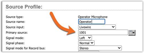
- Assign Logic For. Select Livewire from the drop-down list. In our example, the Operator Microphone is Livewire channel 1001. Studio Mic 1 is Livewire channel 1002. Etc.
- Enter the Livewire Channel. Enter the Livewire channel for each device where GPIO is required.
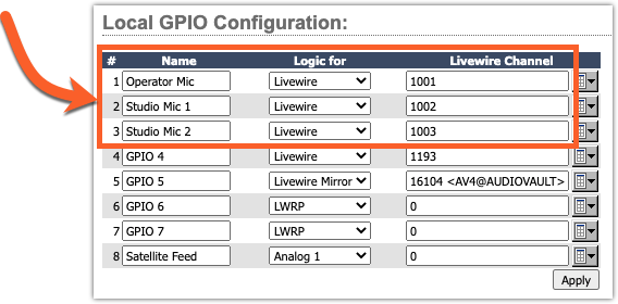
- Click Apply.
As in our local source GPIO, the GPIO is applied when you click apply and it makes no difference where this source is loaded. Unlike the local GPIO above, Livewire GPIO is applied system-wide. The source for the GPIO is not required to be loaded on the same console where the GPIO is configured.
Let us know how we can help
If you have further questions on this topic or have ideas about improving this document, please contact us.