Axia GPIO Pinout
For information about using an external power supply and other application notes, consult the Axia xNode manual's GPIO section.
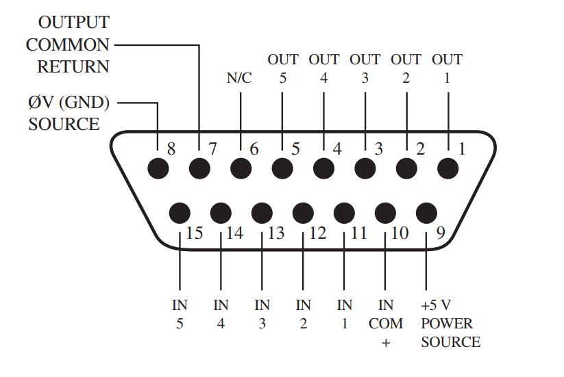
Pins 1 thru 5 are Outputs 1-5
Pin 7 - Output Common Return
This is the reference input for active outputs. When an output is active, the corresponding output pin is connected to this pin. For a closure to ground (low when active), connect this pin to ground (pin 8)
For an Output wiring example, Click Here
Pin 8 - 0V (GND) Source
Ground or negative connection for the internal +5V DC source (pin 9)
Pin 9 - +5V DC Power Source
This pin provides 100mA of current for logic.
Pin 10 - Input Common
This is the reference for the input triggers. When an input is idle, it is the same value as this pin. For normally high active low inputs, connect this pin to the 5V Power source.
Pins 11 thru 15 are Inputs 1-5
For an Input wiring example, Click Here
Specifications:
- Current Limit for inputs = 20mA per input
- Current Limit for outputs = sum shall not exceed 100mA
- Current Limit for 5V Source = 100mA
- Maximum reference input voltage = 24V
Let us know how we can help
If you have further questions on this topic or have ideas about improving this document, please contact us.