Building a GPIO test connector for Axia
 Updated
by
Bryan Jones
Updated
by
Bryan Jones
Scope
Most Axia devices that have a GPIO port also contain a self-test utility. This document details how to build the GPIO test connector for these tests.
Description
When running a self-test on any Axia device where there is a GPIO port, it will be necessary to build a test plug. This plug uses the outputs of the GPIO port to test the inputs. LEDs are used to give you a visual reference as to the status of the ports. These can also be useful in other situations where you might not be running a full test but testing some programming logic.
Building the connector
To construct this connector, you will need;
- 15-pin male "D" connector
- Qty 5 - 20 ms standard 5v LED
- Qty 5 - 180 to 200-ohm resistors
- Hookup wire for jumpers
- Soldering tools
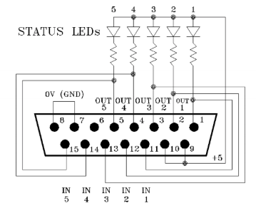
Here is the schematic showing the wiring of the test connector. If you would like to download a PDF of this drawing, click here.
Let us know how we can help
If you have further questions on this topic or have ideas about how we can improve this document, please contact us.