GPIO for the PDM
 Updated
by
Bryan Jones
Updated
by
Bryan Jones
Scope
This document applies to the 25-Seven PDM and specifically covers wiring and use of the GPIO Parallel Port connections.
GPIO
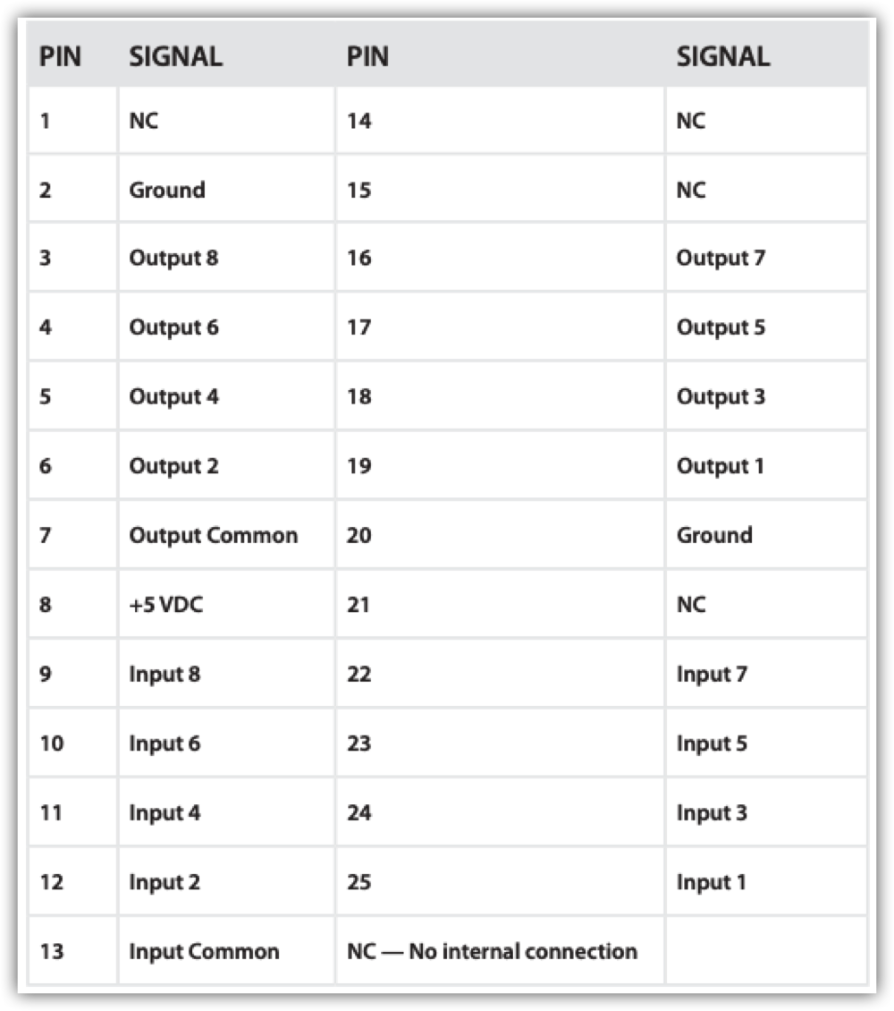
Eight parallel control inputs and eight parallel control outputs appear on the female DB-25 connector, with pinouts detailed below. Use the GPIO menu on the front panel to assign Input and Output functions. Please reference the full PDM Manual for information on the use of the menus.
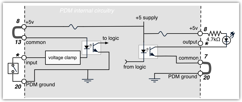
Inputs and outputs are opto-isolated for easy interface to other equipment. A +5v supply and ground are also brought out to the DB-25 for simple remote controls using pushbuttons and LED status readouts. If an output signal is a pulse, its opto-isolator will turn on for between 100ms and 1000ms (adjustable on the configuration screen). The factory default is 250ms.
The +5v supply can provide 200 mA of current. This amount is more than adequate for eight LEDs and eight logic inputs. The total draw should not exceed 200 mA. There is an internal, self-resetting thermal circuit breaker that protects the power supply. If this breaker should trip, power off and allow several minutes for it to cool down and reset.
Basic remote control
- Use the connections shown on the left side of the schematic below. At the DB-25, jump pin 13 (input common) to pin 8 (+5v).
- Connect one side of an SPST NO pushbutton to pin 20 (ground); connect the other side to pin 25 (Input 1).
- Add up to 7 more pushbuttons as needed, connecting one side of all to pin 13 as common, and connecting their other sides to the individual inputs in the chart below.
Basic remote readout
- Use the connections shown on the right side of the schematic. At the DB-25, connect pin 7 (output common) to pin 20 (PDM ground).
- Connect a 4.7 kΩ 1/4 watt resistor between pin 8 (+5 V) and the anode or + lead of an LED; connect the cathode or – lead of the LED to pin 19 (output 1).
- Add up to seven more resistor-and-LED combinations as needed, using pin 8 as the common voltage supply and connecting the LED cathodes to individual outputs indicated in the chart below.
Connecting to external logic or relay circuits:
PDM’s GPIO inputs and outputs are isolated from its power supply and ground, and can be connected to external logic circuits or the power supplies in remote equipment:
- Inputs require at least 6 mA flowing from the input common (pin 13) and the individual input circuit pin.
- Outputs can carry up to 25 mA, up to 30 V DC per channel, between the individual output circuit pin and output common (pin 7).
GPIO Pinouts
Let us know how we can help
If you have further questions on this topic or have ideas about how we can improve this document, please contact us.