Line Ringing Indicators and VX
Scope
How to set up an external indicator for when a line is ringing in a VX studio.
In this example, we will configure the Livewire GPIO in a VX Studio to trigger an output when a line is ringing. This GPO can then be wired to an external lamp which will indicate the presence of a ringing line.
Configure GPIO in the VX Studio
- Using your connected browser, navigate to the desired VX Studio configuration page.
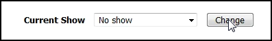
- Set the Current Show to No Show to allow configuration changes
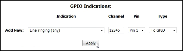
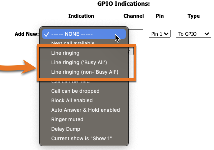
- Under the GPIO Indications section, select the desired indicator from the Add New drop-down list. In this example, we will configure an output for when any of the lines in the Studio are ringing.
- Enter a Livewire channel number into the Channel field to be used for the GPIO and select the output pin. Here, we will use channel 12345 and we will be controlling output pin 1 of the GPIO port.
- Since we are sending a closure command to a node, select To GPIO for Type.
- Click Apply and re-assign the Show to the Studio using the Current Show drop-down box and the Change button.
Which Line Ringing indicator should I use?
There are three options:
- Line Ringing or Line Ringing (All)
- Busy-all Line Ringing
- Non Busy-All Line Ringing
Line Ringing or Line Ringing (All)
If ANY of the Lines are ringing the assigned GPIO logic will become LOW.
When the ALL of the lines are NOT ringing, the GPIO logic will become HIGH
Busy-all Line Ringing
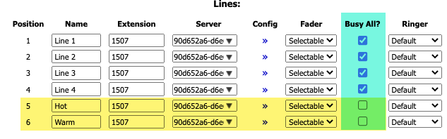
Only Lines that have the "Busy ALL" checkbox checked are ringing will cause the assigned GPIO logic will become LOW.
When all lines that have "Busy ALL" checkbox checked are NOT ringing, GPIO logic will become HIGH
Non Busy-All Line Ringing
Only Lines that do not have the "Busy ALL" checkbox checked are ringing will cause the assigned GPIO logic will become LOW.
When all lines that have do not "Busy ALL" checkbox checked are NOT ringing, GPIO logic will become HIGH
Configure the physical GPIO port
Once you've located an available port on a GPIO node, Powerstation, QoR Engine, or Element GPIO/PSU, go to its configuration web page to configure the port. In this example, we'll use a QoR Engine, but other devices are configured in a similar manner.
- In your connected browser, navigate to the GPIO page of the QOR.
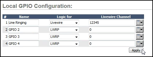
- Select a port under Local GPIO Configuration, label it, set it for Livewire and enter the channel number you configured in the previous steps
- Click Apply
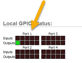
At this point, you could test by calling into the studio and observing the Local GPIO Status indicators.
Wire up the GPIO port
- Connect pin 7 (Output Common) to pin 8 (Ground). This configures the outputs to close to ground when active.
- Connect pin 9 (+5V DC) to one side of the relay's coil.
- Connect pin 1 (Output 1) to the other side of the relay coil (with appropriate flyback diode).
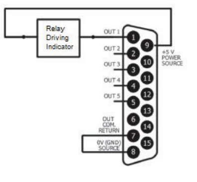
- Use the N.O. contacts of your relay to drive the indicator you have.
Let us know how we can help
If you have further questions on this topic or have ideas about how we can improve this document, please contact us.