Replacing the switchboard in an Axia PowerStation Integrated Console Engine
 Updated
by
Bryan Jones
Updated
by
Bryan Jones
Scope
This document covers the removal and installation of the Axia switchboard (part # 1701-00239) in an Axia PowerStation (2001-00251)
Tools Required
The following tools will be required to complete this procedure.
- Axia Document on removing the cover of the PowerStation
- Axia Document regarding the proper pairing of the internal switch and I/O board
- #1 Phillips screwdriver
- #2 Phillips screwdriver
- 3.0mm Allen wrench
- A small pair of needle-nose pliers
Removing the Switchboard.
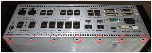
Using a Phillips screwdriver, remove the seven Phillips head screws from the back panel on the underside of the PowerStation as shown.
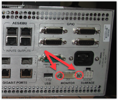
Using needle-nose pliers, remove the two studs from either side of the DVI Monitor connector as shown.
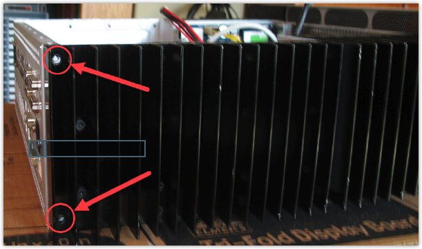
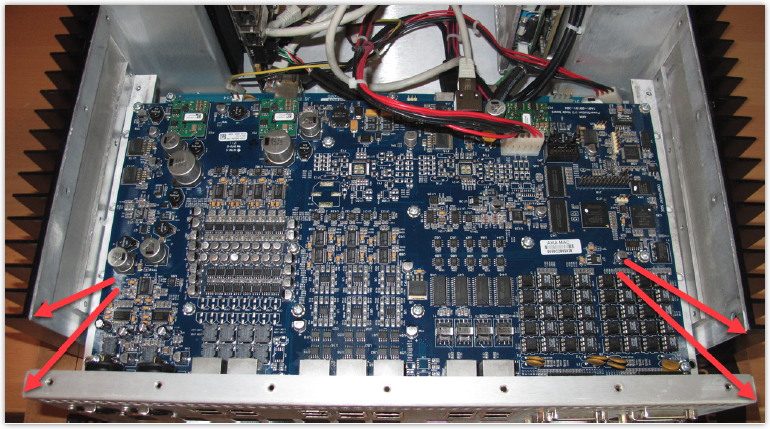
Using a 3.0mm Allen wrench, remove the 4 Allen screws (two on each side), holding the back panel to the chassis as shown.
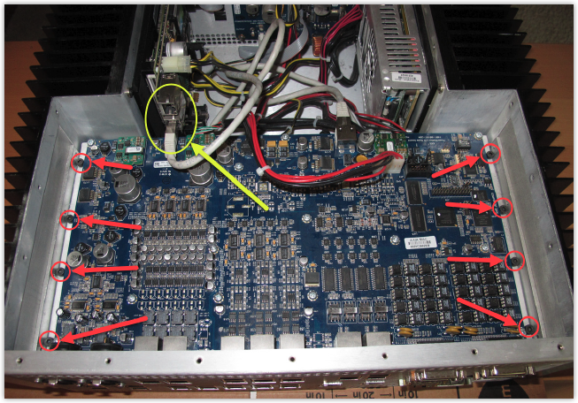
Using a 3.0mm Allen wrench, remove the eight screws from the inside of the PowerStation that hold the upper I/O board to internal “L” brackets, as shown in the photo below.
Also referencing the photo below, disconnect the network cable marked in YELLOW from the lower connector of the CPU board to allow the I/O board to be moved out of the way more easily.
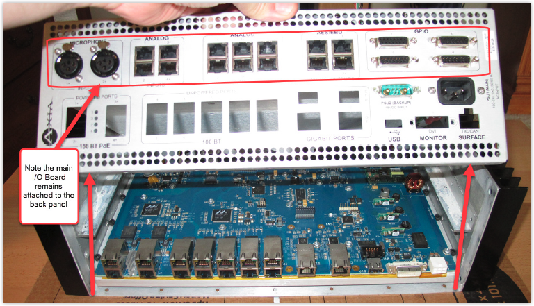
With those screws removed, the back panel (with the I/O board still attached) can be moved toward the rear and then lifted up and out of the way, as shown.
Disconnect the following cables;
(A) Yellow and black 48-volt power cable
(B) I/O board network connection. This cable is installed in the lower of two connectors.
(C) HDMI video connector
(D) CPU board network connection
(E) Main power connector
(F) USB connection - note silicone glue on this connector is not needed when reinstalled
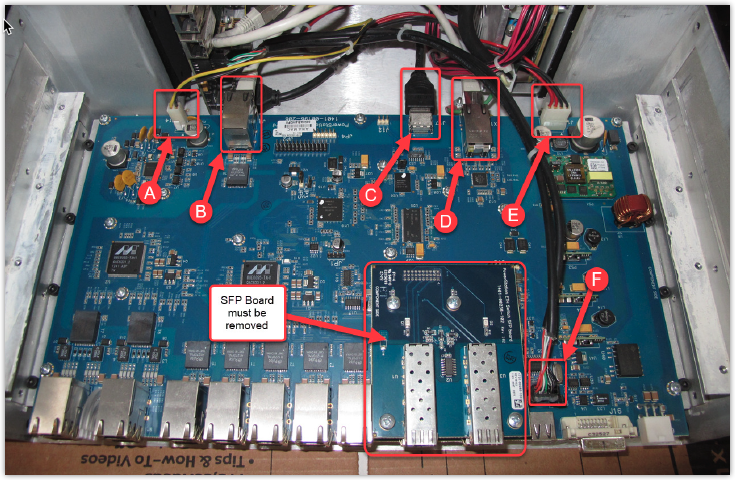
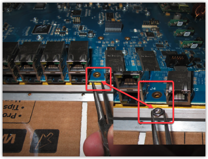
Remove the PowerStation ETH Switch SFP Board as shown in the following picture.
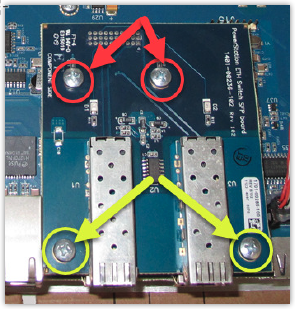
There are four Phillips-head screws that must be removed. The two marked in RED have a threaded stud that is mounted to the metal backing plate. The two marked in YELLOW have a loose nut that is under the switchboard. Use a set of needle nose pliers to grasp the nut for removal and re-installation.
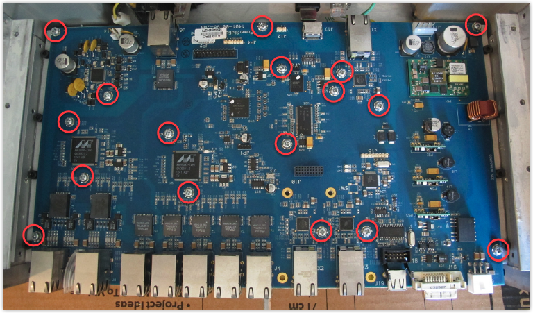
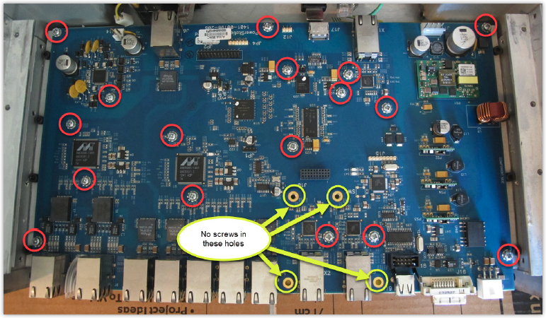
Remove the seventeen Phillips head screws shown in the following picture that holds the switchboard to the aluminum mounting plate.
Gently lift the board up and away from the aluminum mounting plate.
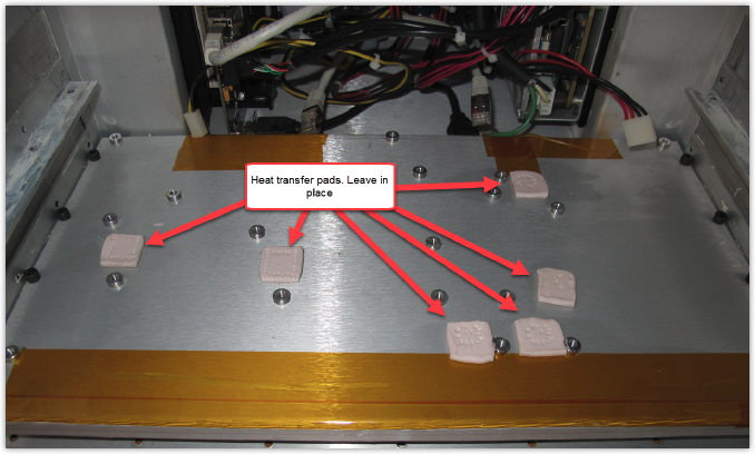
If the pads remain stuck to the metal mounting plate, leave them in place and do not remove them. This is shown below.
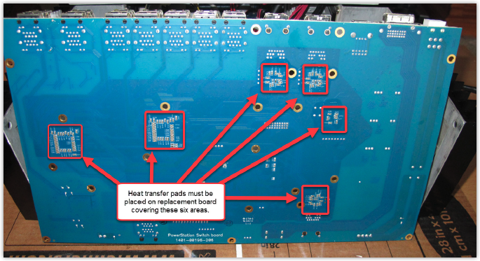
If the heat transfer pads remain stuck to the switchboard they MUST be removed and placed in the same positions on the replacement board. Note the pads can be carefully peeled off the board and placed on the new one.
Reinstall the replacement switchboard in reverse order
Place the replacement switchboard with heat pads attached on the metal mounting plate and secure it with seventeen Phillips head screws.
As a reminder, do not place any screws in the holes used to mount the SFP board.
Reinstall the SFP board taking care to properly align the pins on the SFP board with the connector on the switchboard. It is helpful to place the standoffs over to holes on the board first then align the two connectors. Once installed, install the two rear Phillips screws as shown.
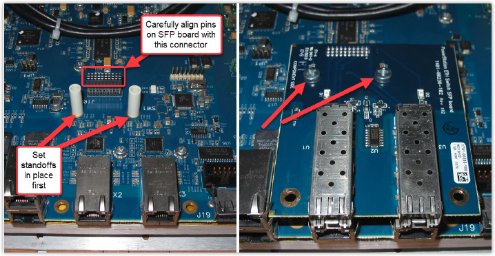
Using a pair of needle-nose pliers, place the two remaining standoffs under the remaining two holes of the SFP board. Install the remaining two Phillips screws using the needle-nose pliers to place the nuts on the screws. Note that the nuts are installed between the main switchboard and the metal mounting plate.
Re-attach cables A thru F paying attention to the proper orientation of the cable.
Move the I/O Board and rear panel assembly back into place, checking for proper fit of the ethernet connectors into the cutouts. A network cable can be inserted in the network jacks to move them gently. This will aid in alignment.
- Install all screws loosely and then tighten.
- Reinstall the eight screws on the inside (4 on each side of the I/O board).
- Reinstall the four side screws (two on each side) to the back panel.
- Reinstall the seven Phillips screws that attach the back panel to the bottom.
- Reinstall the two standoffs on either side of the DVI monitor connector and tighten with needle-nose pliers.
- Reinstall the network cable that was removed from the bottom RJ45 connector of the CPU Board.
Final Steps
- Double-check that all cables have been properly attached.
- On the underside of the PowerStation, you will find three MAC Address stickers. Compare the sticker from the board you removed and remove the same sticker from the bottom of the unit. If your new board came with a new MAC Address sticker, replace it with the one from the new board.
- After powering the unit up you must perform the steps found in the document referred to earlier regarding the proper pairing of the internal boards.
- Reinstall the cover and place your unit back in service.