Replacing a Quasar motorized fader
 Updated
by
Bryan Jones
Updated
by
Bryan Jones
Scope
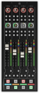
Should a Quasar motorized fader become damaged, defective, or otherwise require maintenance, this document details the removal process. This document only applies to the XR module of Quasar modules and covers replacing a single fader, not the entire fader module.
- 2001-00569-000: Quasar XR-4FAD Module, Motorized
Description
The process of removing and replacing a fader on a Quasar module requires the following tools;
- 2mm Allen wrench
- 2.5mm Allen wrench
- #1 Phillips screwdriver
- (suggested) Anti-static wrist strap.
Removal
Removing the module from the frame
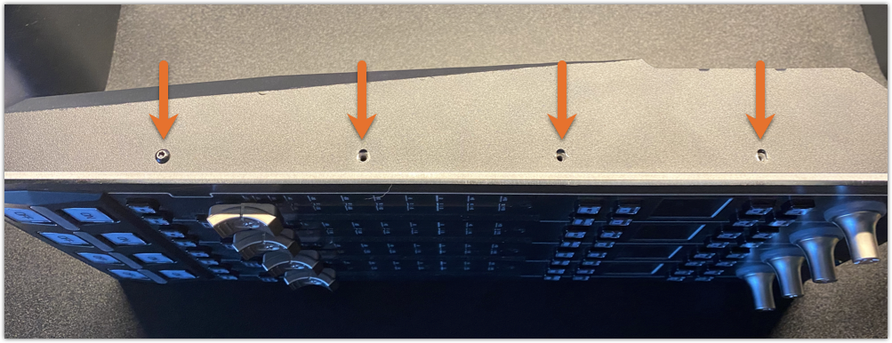
- Using a 2.5mm Allen wrench, remove the two screws at the top of the XR four-fader module.
- Carefully lift the top of the module up and away from the frame. The bottom of the module rides in a track. The module will "hinge" from the bottom.
- Disconnect the two ethernet cables and any power cables.
- Lift the module out of the frame and take it to a suitable anti-static work surface.
Module Disassembly
- Using a 2mm Allen wrench, remove the four screws on either side (eight total) of the module.
- On the underside of the module, remove the case screw next to the Ethernet ports.
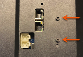
These are for the internal heat sync and must remain attached to the rear cover.
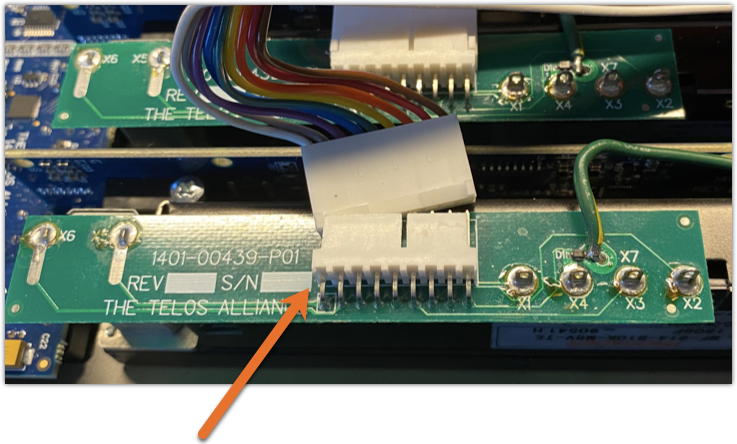
- There is a ground wire from each fader to a post near the top of the assembly. Using a #1 Philips, remove this screw.
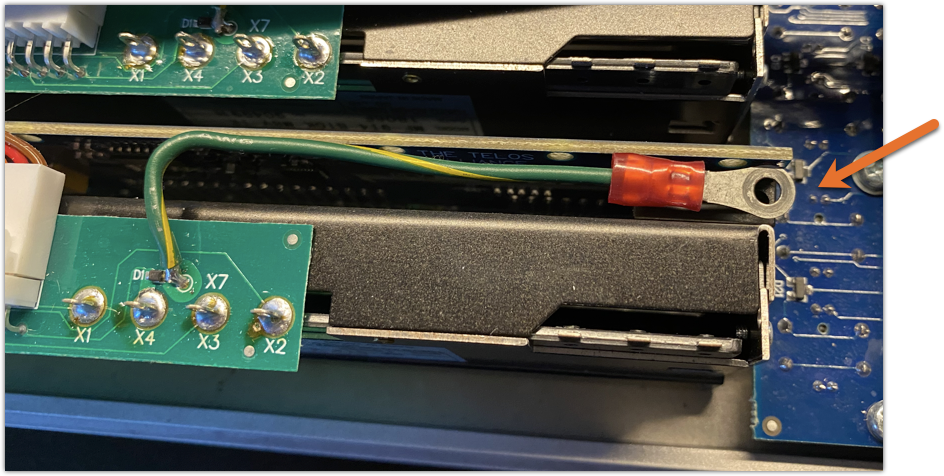
- Carefully unplug the nine-pin connector shown here.
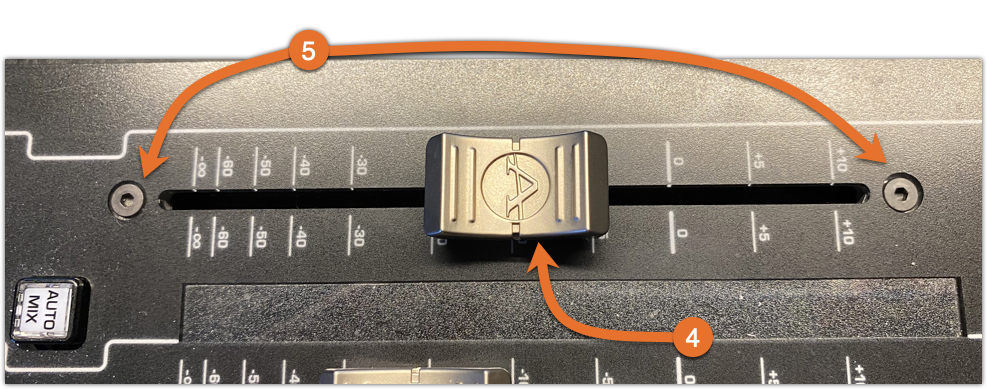
- Turn the module over to the front and remove the fader knob.
- Using a 2mm Allen wrench remove the screw at the top and bottom of the fader.
- Remove the fader from the backside of the module.
Reassembly
Reassemble the module in reverse order.
Calibration
All fader module assemblies are calibrated at the factory. Should you find that this newly re-installed fader is out of calibration with the other faders in this SAME module, follow this fader calibration procedure.
Let us know how we can help
If you have further questions on this topic or have ideas about improving this document, please contact us.