Even though all bios settings are shown here for reference, only a few changes are required. Those are noted in RED
To replace the CMOS battery [CR2032 (+3 Volts) BOTH BOARD TYPES] in an Axia GPIO/PS unit, it is necessary to reset all of the BIOS configurations, including the option to boot the motherboard when power is applied to the unit. Since this configuration is lost when the battery is removed, it is necessary to short the power pins on the board to start the computer after the new battery is installed.
First Start
EPIA-M Example
Attach a keyboard and monitor to the internal connections on the motherboard. Short the PWR pins 6 and 8 pins to boot the unit.
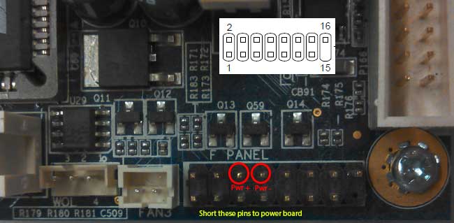
NANO Example
Resetting the BIOS configurations
VIA EPIA-M board (no USB)
To program BIOS for the VIA EPIA-M motherboard in the Element GPIO you will need:
A keyboard w/PS2 connector
A Monitor
Connect keyboard to the proper jack.
Connect power and using a small screwdriver short pins 6 and 8 together on the connector “Fpanel” (front right corner) to simulate a power on button press. Note that Pin 15 is missing from header.
Immediately after shorting the pins keep tapping the “DEL” key until the BIOS config screen appears.
STANDARD CMOS SETTINGS
DATE
[mm:dd:yy]
TIME
[24 hours format]
IDE PRIMARY MASTER
[COMPACT FLASH CARD]
IDE PRIMARY SLAVE
[NONE]
IDE SECONDARY SLAVE
[NONE]
Drive A
[NONE]
Drive B
[NONE]
Halt On
[ALL, but keyboard]
ADVANCED BIOS FEATURES
Virus Warning
[Enabled]
CPU l2 Cache ECC Checking
[Enabled]
Quick Power On Self test
[Enabled]
First Boot Device
[HDD-0]
Second Boot Device
[Disabled]
Third Boot Device
[Disabled]
Boot Other
[Disabled]
Swap Floppy drive
[Disabled]
Boot up Floppy seek
[Disabled]
Boot up NumLock Status
[On]
Typematic rate Setting
[Enabled]
Typematic rate (Chars/sec)
[30]
Typematic delay
[250]
Security option
[Setup]
Display Full Screen Logo
[Enabled]
Show summary info
[Disabled]
Display Small logo
[Disabled]
ADVANCED CHIPSET FEATURES
AGP Aperture size
[128meg]
CPU to PCI Post Writer
[Enabled]
Select Display Device
[CRT] (even if it will be an LCD)
Panel type
[1024*768]
TV type
[NTSC]
CPU Direct access FB
[Enabled]
INTEGRATED PERIPHERALS
Super IO DEVICE
Onboard FDC Controller
[Disabled]
Onboard Serial port 1
[3F8/IRQ4]
Onboard Serial port 2
[2F8/IRQ3]
Onboard Parallel port
[378/IRQ7]
Parallel port mode
[SPP]
Onboard IDE Channel 1
[Enabled]
Onboard IDE Channel 2
[Enabled]
IDE Prefetch Mode
[Enabled]
Display Card Priority
[AGP]
Frame Size Buffer
[16M]
AC97 Audio
[Disabled]
MC97 Modem
[Disabled]
VIA OnChip Lan
[Enabled]
USB Keyboard Support
[Disabled]
Onboard LAN Boot ROM
[Disabled]
Onboard Fast IR
[Disabled]
POWER MANAGEMENT SETUP
ACPI Suspend Type
[S1 (POS)]
HDD power down
[Disabled]
Power Management Timer
[Disabled]
Video Off Option
[Always ON]
Power Off by PWRBTN
[Instant OFF]
Run VGABIO if S3 Resume
[Auto]
AC Loss Auto Restart
[ON] (**Important**)
PERIPHERALS ACTIVITIES
VGA Event
[OFF]
LPT & COM Event
[LPT/COM]
HDD & FDD Event
[ON]
PCI Master Event
[OFF]
PS2KB Wakeup Select
[Hot Key]
PS2KB Wakeup from S3/S4/S5
[Disabled]
USB resume
[Disabled]
Power On by PCI Card
[Disabled]
Wake on LAN/RING Connector
[Disabled]
RTC Alarm Resume
[Disabled]
IRQ ACTIVITIES
Primary INTR
[ON]
IRQ3 (COM 2)
[Disabled]
IRQ4 (COM 1)
[Enabled]
IRQ5 (LPT2)
[Enabled]
IRQ6 (Floppy Disk)
[Enabled]
IRQ7 (LPT1)
[Enabled]
IRQ8
[Disabled]
IRQ9
[Disabled]
IRQ10
[Disabled]
IRQ11
[Disabled]
IRQ12 (PS/2 Mouse)
[Enabled]
IRQ13 (CoProcessor)
[Enabled]
IRQ14 (Hard Disk)
[Enabled]
IRQ15 (Reserved)
[Disabled]
PNP/PCI CONFIGURATION
PNP OS installed
[NO]
Reset Config Data
[Disabled]
Resources controlled by
[Auto (ESCD)]
Assign IRQ for VGA
[Enabled]
Assign IRQ for USB
[Enabled]
Save BIOS and exit
VIA NANO M-830 board
To program BIOS for the VIA NANO motherboard in the Element GPIO you will need:
A keyboard w/USB connector
A Monitor
Connect USB keyboard to the any of the USB ports.
Connect power and using a small screwdriver short the PWR (power) pins together on the connector “F PANEL 1” (front right corner) to simulate a power on button press.
Immediately after shorting the pins keep tapping the “DEL” key until the BIOS configuration screen appears.
 Updated
by
Bryan Jones
Updated
by
Bryan Jones