Logic that allows a single button to execute a different action on each press
 Updated
by
Brett Patram
Updated
by
Brett Patram
Scope
This HelpDoc will dive into the topic of utilizing numeric memory slots to allow a single user button to execute through a predefined list of actions.
This document is for users of Pathfinder Core PRO.
Description
Here is the problem we are trying to solve for:
"I have a User Button on my console (imagine this is a Fusion LCD 10 button module, Quasar MTS user buttons or router control panels)
When I push the button the first time I want to route Program 1 of the console into the air chain.
When I push the same button a second time I want to route my automation playback audio into the air chain.
If I press the button a third time I want to put the studio live again, and so on in a loop"
The problem above can be solved in part by using a Numeric Memory Slot in Pathfinder. Numeric Memory Slots are unique, they offer these key features: The value of the memory slot can be incremented or decremented (addition or subtraction math), the memory slot can have a preset range it must be within, the memory slot can loop or rollover if the upper or lower limit of that range is reached.
You can take a User Button and bind the "mousedown" state so that it adds 1 to the numeric memory slot value. Each press of the button keeps adding 1 to the value, until the upper limit is reached and it rolls over. This allows you to "cycle" through sequential numbers in a loop (Example: 0,1,2,0,1,2,0,1,2...)
Logic Flows (or bindings in User Panels themselves) elsewhere can read this memory slot value. Each possible value of the numeric memory slot can be used to signify a particular state.
We start our example by defining just 2 states:
State 0 = Studio is LIVE
State 1 = Automation audio ONLY (studio bypassed)
In table form, here is what we want the states or memory slot values to do when set:
If Memory Slot Value = 0, then do these things: | If Memory Slot Value = 1, then do these things: |
Route Livewire channel 5009 (Program 1 bus) to DST 3 on an xNode | Route Livewire channel 7012 (Automation mix) to DST3 on an xNode |
Set the Off state color of the button to be Yellow | Set the Off state color of the button to be Green |
Set the User Button Caption to say "LIVE!!!" | Set the User Button Caption to say "STUDIO BYPASS" |
Configuration
Create memory slot
Go to the Memory Slots page and create a new Numeric Memory Slot with the parameters below. Set the Name field to be something relevant to your installation 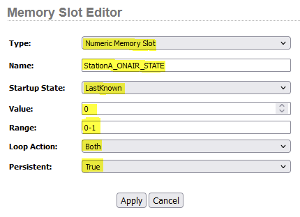 |
Create user panel button
If you have an existing user panel, add a new button onto the canvas. Otherwise, create a new user panel, add a button and save the panel  |
Map user panel button to hardware (optional)
This step is optional if you do not have a hardware user button. However, if you have a hardware button such as those found in Axia Router Control Panels, Element,Fusion and Quasar consoles you will need link them together. A step by step how-to can be found here, look at section "Map the software button to the hardware button" 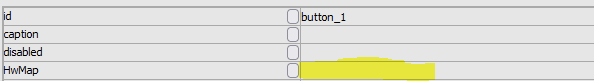 |
Set the "mousedown" action of button
Here we will set the "mousedown" action of the button to increment our numeric memory slot by 1 Click the small button next to "mousedown" under event 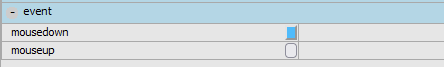 At the bottom of the page select the End Point icon (right side) of the mini logic flow  |
The "Property Selector" window appears. Expand Memory, find the name of your Numeric Memory Slot and expand that too. Choose "Increment" as the Property. 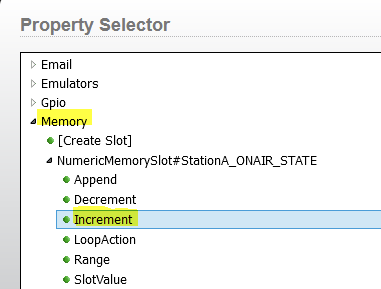 Click the Select button. |
The "Translator Properties" window will appear. Click on the first default translator line *=* to highlight it. We want to modify the first line so that it is set as True = 1. 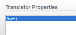 Click Done on the "Translator Properties" window |
Save your changes to the user panel  |
Set the "backcoloroff" property of button
If these steps are being followed in order, clicking OK on the Translator Properties window from Step 4 will bring up this question prompt Click Cancel 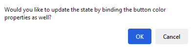 |
Click on the small button next to "backcoloroff" property  |
At the bottom of the page, select the End Point icon (right side) of the mini logic flow  |
The "Property Selector" window appears. Expand Memory, find the name of your Numeric Memory Slot and expand that too. Choose "SlotValue" as the Property.  Click the Select button. |
A "Translator Properties" window will appear. We want to add in two translator lines. The first one will set the button's off state color to yellow if memory slot value is 0 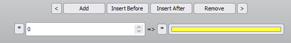 The second one will set the button's off state color to green if memory slot value is 1 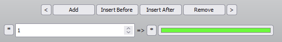 Both lines will be listed referencing the RGB values equal to Yellow and Green 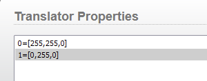 Click Done on the "Translator Properties" window |
Save your changes to the user panel  |
Why not fix the "backcoloroff" property to Yellow, and "backcoloron" property to Green? Then use the memory slot value to set the button indicator to ON and OFF?
Answer: You could do this! If you only have 2 states (0 and 1), it makes sense. Even more so, using a Latching Memory Slot when there are only 2 states also makes more sense here. If this is exactly and only what you want to do, take a look at This HelpDoc
The larger picture of this HelpDoc is to show you that you can have more than just 2 states. Stay with us here, at the end of this doc we will show you the extra functionality this unlocks for you beyond this 2 state only example
Set the "caption" property of button
Click the small button next to "caption" property  |
At the bottom of the page select the End Point icon (right side) of the mini logic flow |
The "Property Selector" window appears. Expand Memory, find the name of your Numeric Memory Slot and expand that too. Choose "SlotValue" as the Property. Click the Select button. |
A "Translator Properties" window will appear. We need two translator lines. Click on the first default translator line *=* to highlight it. Modify it as shown below, 0= LIVE!!!. Click the Add button 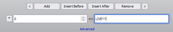 Modify the second line so that it appears as 1 = STUDIO BYPASS 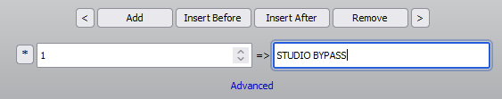 The Translator Properties list should like this: 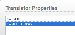 Click the Done button |
Save your changes to the user panel  |
Create a Logic Flow outside the user panel
So far we have the button press incrementing the memory slot value on each press. We have the button color and caption also changing per memory slot value.
Now we will use a Logic Flow outside of the user panel, and have the memory slot value perform a route change. A different Livewire channel number will be routed depending on the memory slot value we have
Go to the Logic Flows page and create a new logic flow Double Click on the Start Point (Left Icon)  |
The "Property Selector" window appears. Open Memory, find the name of your Numeric Memory Slot. Choose "SlotValue" as the Property. Click the Select button. |
Double Click on the End Point (Right Icon) 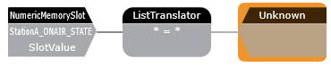 |
The "Property Selector" window appears. We are going to find a Destination of an xNode that feeds audio to our studio transmitter link. Expand Routers, expand Axia Audio, Find the Destination that corresponds to the Device and Destination we wish to make the change to. Expand that. Select CurrentSourcePath In my example I have an xNode on 10.0.18, Destination #1 which is named STL INPUT, is what I want to make the change to I selected the "CurrentSourcePath" property. However you could also select "CurrentChannelNumber" property Using "CurrentSourcePath" will give us a dropdown menu in the List Translator windows, to help find Livewire Source we want to Route to the xNode Destination Using "CurrentChannelNumber", you will need to know the Livewire channel number. The List Translator will expect a numerical value provided by you 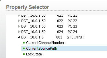 Click the Select button |
Double click on the List Translator (middle icon) 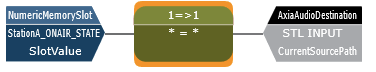 |
A Translator Properties window will appear. We want to add in two translator lines. Click on the first default translator line *=* to highlight it We want to modify the first line so that it is set as 0= The Source we wish to route to the xNode destination. Click the Add button For my example here, this will route Program 1, Livewire channel 1001, from an Axia Studio Engine to the xNode Destination when the memory slot value is equal to 0 (this is our live studio audio) 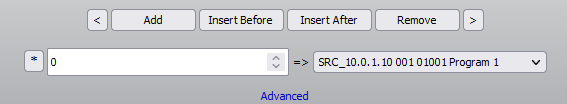 Modify the second line so that it appears as 1 = The Source we wish to route to the xNode destination For my example here, the will route VMIX 1 sub mix, Livewire channel 216, from an Axia Studio Engine to the xNode Destination when the memory slot value is equal to 1 (this is our automation only audio mix) 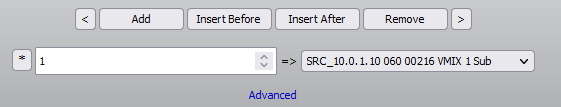 Here is what the two entries should look like. The first entry might not show the Source name correctly, this is just a display bug. 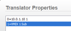 Click Done on the Translator Properties window |
Apply your changes to the logic flow page 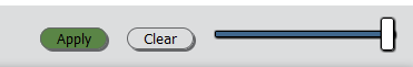 |
At this point we are done. The moment you applied the above logic flow, the Destination on the xNode should have been set if the Memory Slot value was 0 or 1.
Test it out
Let's verify and review everything is working as expected
Launch the User Panel you created. Go to the User Panels page and click the Window icon next to the panel name you are using 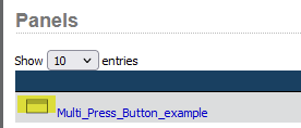 |
Press the button several times, we should see several things change on each press The Caption on the button should change between "LIVE!!!" and "STUDIO BYPASS" The color of the button should change between Yellow and Green  The Memory Slot Value should change between 0 and 1  The Logic Flow should be setting the Route of Program 1 or VMIX1 Sub to the xNode destination  The xNode destination, as seen from the xNode web gui, should also change between channel number 1001 and 216 (you will need to refresh the web page to see the changes)  |
Expanding on this concept
With the principal concepts outlined here, you can do so much more than this example, and you can do it with just ONE button. Consider changing the Numeric Memory slot range from 0-1 to 0-4 -- now you have 5 possible states to rotate through Consider changing the button caption and colors to display differently for each of those 5 states Consider changing the Logic Flow to perhaps allow 5 different Livewire channels route to an IP Driver destination. The above expansion could allow a user to select through 5 common record sources for their audio editing PC input  |
In closing a couple popular uses:
- Changing the audio source feeds to codecs on the fly
- Switching between common console show profiles
- Switching between VX Show's for a specific VX Studio to use
- Toggling different GPO pin pulses to trigger remote equipment to step through different modes (3rd party mic processor preset recall, lighting controls, etc)
- Cycling through various air feeds in your cluster for board operator confidence checks during overnight shifts (do those exist still?)
Let us know how we can help
If you have further questions on this topic or have ideas about improving this document, please contact us.