Controlling Routing and lamp status with a GPIO button
 Updated
by
Bryan Jones
Updated
by
Bryan Jones
Scope
This document covers Pathfinder Core Pro configuration as it relates to routing and the status of the buttons used for routing.
Description
IBuilding GPIO buttons (physical buttons wired to a GPIO node) to control routing is possible. These buttons might be used to control what feeds a transmitter or act as a studio switcher.
In this document, we will cover two items.
- How to use the Button to change the route when pressed
Wiring GPIO
How to use the status of the route to control the lamp status (if your PGPIO button has an indicator lamp)
We will not cover here, as it's covered elsewhere, how to wire up a GPIO port. If you are here, we assume you know how to solder or otherwise connect the GPIO to your Button. This GGPIO examples Help Document is exactly what we are going to be doing here: https://support.telosalliance.com/article/dgfmzj9h6t-axia-gpio-basic-examples There is an input device, your Button, and an output device, your button lamp.
Controlling the route
From a descriptive standpoint, our logic flow will monitor the state of the GPI on the node. That will go LOW when the button is pressed and will route the desired source to the destination on the node that feeds our STL.
- In Pathfinder Core Pro, create a new blank logic flow by clicking the Green Add New + (plus) icon.
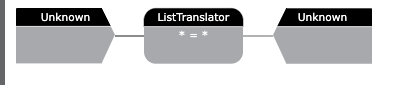
You are presented with a basic, blank logic flow showing the input to the flow on the left. The Translator is in the middle, and the output is on the Right.
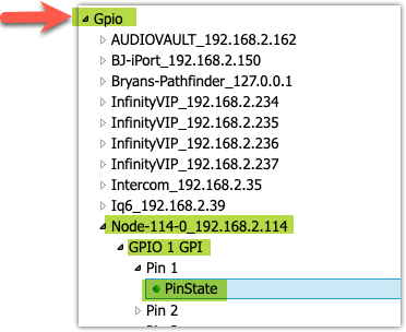
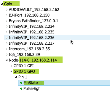
- Double-click the input block of the translator. Use the small arrow next to each device to expand that group. Drill down in the tree to the Individual Pin state. In our case, GPO port 1 GPI pins, Pin 1, then pick the PinState property. Then click Select.
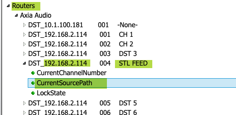
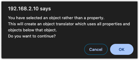
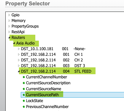
- Double-click the OUTPUT block (not the Translator yet). Similar to the GPIO, expand Routers, expand Axia Audio, and expand the DST on the node that feeds your Transmitter (ours is labeled STL FEED). Then, pick Current Source Path. Then click Select.
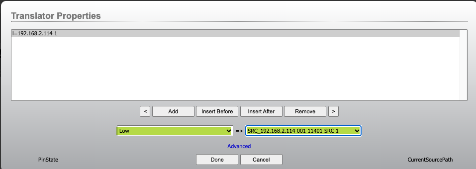
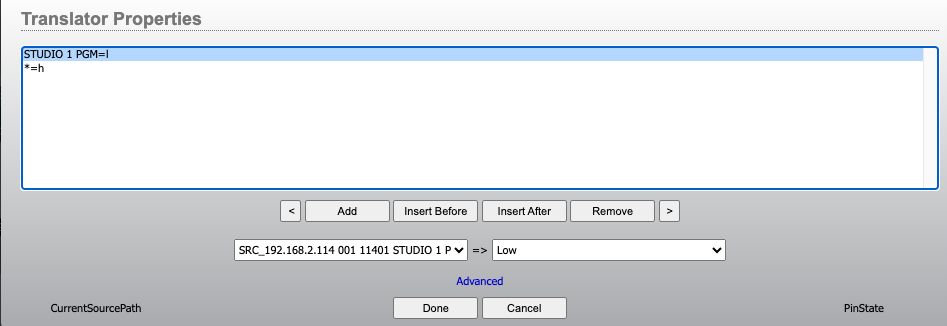
- Double-click the Translator block. Click the *=* in the list of Translators (it's there by default). Select Low from the drop-down list for the input side of the Translator. Select the source you want to be routed to the node when the Button is pressed (in our example, it's channel 11401. Once you have those selected, click Done.
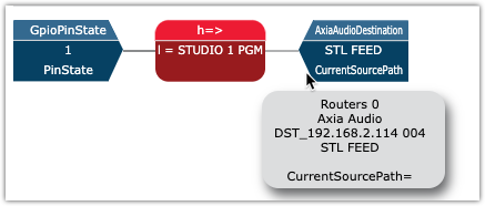
Here is the completed Logic Flow
Controlling the lamp
We will use the Route status to control the lamp. We don't want to turn the Button's lamp on just because you pressed the Button. We want the lamp to reflect the state of the route. The route might get changed by other things (an automation system, for example). This way, the lamp indicates the state of the route no matter what made the route.
The steps here are the same as above, but we'll use the route state as the input to the flow and the GPO that drives the lamp as the output. The Translator will set the lamp GPO Low (on) when the route is channel 11401.
- n Create a new blank logic flow by clicking the Green Add New + (plus) icon
- Double-click the input (left) side of the new Logic Flow. From the Property Selector, expand Routers, Axia Audio, then the DST on the node and select Current Source Path. Then click Select.
- Double-click the OUTPUT block (not the Translator yet). Expand GPIO, locate and expand the GPIO node; this time, select the GPO (Outputs) Pin 1 Pin State. We picked Inputs in the first example; we need GPO (outputs now) to control the lamp. Click Select.
- Double-click the Translator block. Click the *=* in the list of Translators (it's there by default). This time, select the source you routed in the previous step from the list as the input. Select Low on the output side (this turns the output on whenever our source is 11401.
- In this case, we need to add one more condition. Click ADD to add a new translation. Then click on the *=* that is added to slec it. From the list of sources, pick the * from the top of the list. Pick High (off) for the output side.
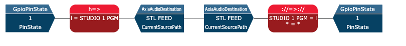
The finished pair of logic flows looks like this. It is normal for them to be connected together as the DST is the same.
Creating other buttons and routes
You will likely have other buttons and other routes. Repeat these steps for those other buttons and routes. Each button and its status will have its own pair of logic flows.
Let us know how we can help
If you have further questions on this topic or have ideas about improving this document, please contact us.