Using the Self Test mode in an iQ QOR Engine
 Updated
by
Bryan Jones
Updated
by
Bryan Jones
Scope
This document applies to the self-test procedure built into the QOR32 and QOR16 Axia iQ console engines. It is intended only as a diagnostic tool to separate hardware problems from configuration issues. There is no repair information provided here based on the results of the test.
This test procedure will put full volume tone on the QOR outputs and potentially damage any amplified equipment like speakers or headphones. DO NOT PERFORM THIS TEST WITH ANY AUDIO CABLES CONNECTED TO YOUR QOR. Only connect cables as instructed by the test procedure.
Description
This test procedure will test all aspects of I/O on the QOR. Certain tests require special cables, as noted.
- All Mic Inputs (Test cable required; click here for information)
- All Analog Inputs
- All Analog Outputs
- All AES Inputs
- All AES Outputs
- All GPIO ports (Test fixture required; click here for information)
- All Canbus connectors (connectors are not so common, this test is generally skipped)
Additionally, you will need eight standard RJ45 cat-5 cables used as audio jumpers. Outputs are connected to inputs that test both circuits. As a part of these tests, you will be instructed when and where to connect these cables.
Connecting to the QOR
First, ensure all audio and GPIO cables are disconnected from your QOR. Your QOR should be connected to AC Power and a single network cable.
- Using a terminal program like PuTTy (https://www.chiark.greenend.org.uk/~sgtatham/putty/latest.html) for Windows or Terminal for Mac. Make a telnet connection to your QOR on standard telnet port 23.
You will be presented with a command prompt that looks like this.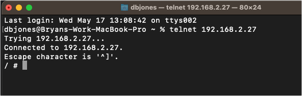
- Change to the test directory. Enter the following command and press enter.
cd /iq/test/
Your prompt will turn to /iq/test # as shown here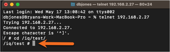
- Enter the following command and press enter. This enters the test mode.
./run.sh
When you press enter a number of lines of text will go by and eventually say DSP Load success as shown here indicating test most is loaded.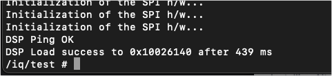
- Enter the following command and press enter. This runs the Livewire test. The -c tells the test to continue and not halt.
./lwt -c
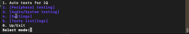
You will be presented with a menu that looks like this.
- Chose 1. Auto test for iQ from this menu.
The test will begin.
It will first perform some basic items like power, network, upper and lower IO board presence, etc. You can observe the lights on the front panel to see if they are all working.
- Press ENTER to continue.
- Next, it will test for GPIO. If you have built a GPIO tester, install it first on Port 1 and follow the steps. Move to port 2, etc. Press ENTER to skip this test.

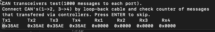
- The CAN Transceivers test is next. Unless you have a loopback cable, press ENTER to skip this test.
- TEST #1 - Next starts the audio tests. Connect the eight Cat-5 RJ45 cables as instructed here.
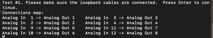
This test will test;
- Noise Floor for Inputs/Outputs
- input/output levels at 20Hz
- input/output levels at 100Hz
- input/output levels at 1kHz
- D/A gain reduction at 1kHz to -6 dB
- input/output levels at 20kHz
- THD for Inputs/Outputs
Results are shown on the screen. Tests that PASS are indicated in green. Tests that FAIL are shown in red. A sample is shown here that shows the current value as well as the expected range of results.

You can see that A-IN 1 (Analog input 1 has failed) and A-IN 2 (Analog input 2) has passed.
A failed test indicates an issue with either the Input or the Output producing the signal.
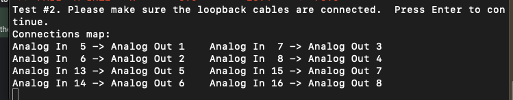
- TEST #2 -After that test is complete, you will be asked to move the cables. Move them as shown here and continue the tests.
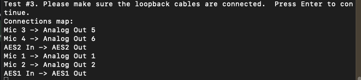
- TEST #3 - AES and Mic tests. Note special cables are required for Mic Tests (noted at the top of this document)
- Once complete you will be returned to this menu. Press 0 to Exit
you will get the message that Work is finished and be returned to the command prompt.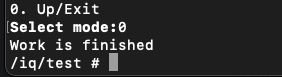
- Reboot your QOR to restore normal operation
Dealing with Errors
In our example, we noted that Analog Input 1 has failed. What we don't know is if the input is defective or the output of the QOR that produces the signal is defective or if you have a bad cable. You can swap cables and repeat the test as many times as you need.
Let us know how we can help
If you have further questions on this topic or have ideas about improving this document, please contact us.